Stop light cycle
Work in Progress
These docs are still a work-in-progress and may not be fully baked just yet! Please contact me if any of it seems very wrong or needs extra clarification.
Steps
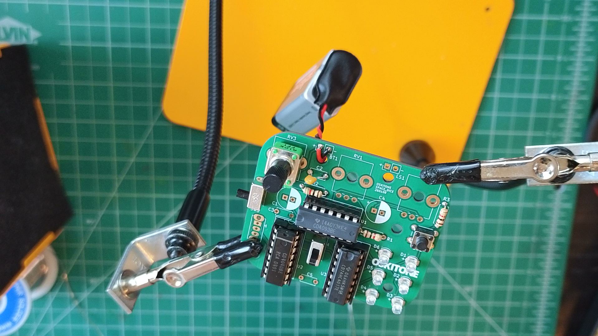
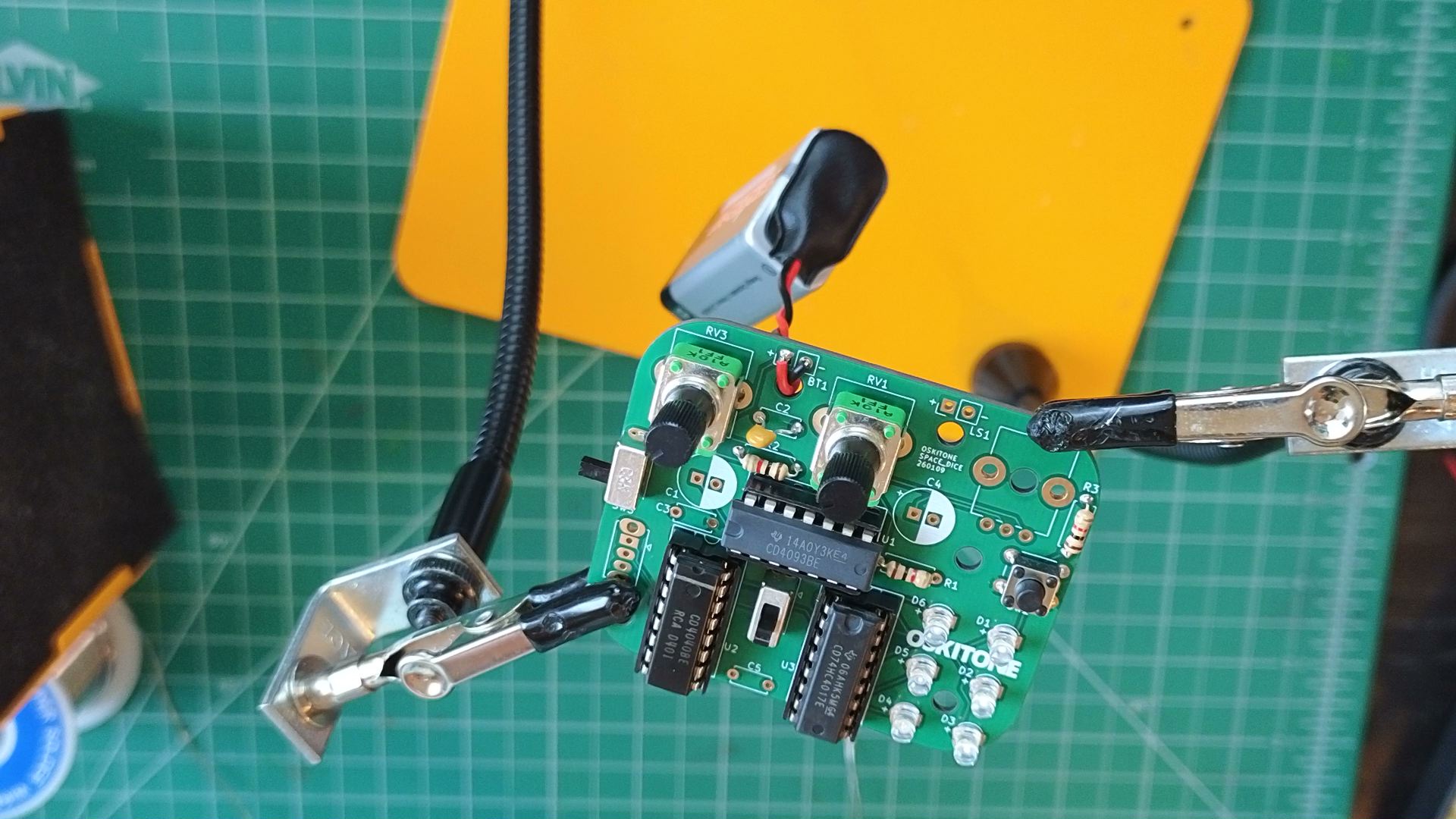
- Solder 1k resistor to R1.

- Solder 10k potentiometer to RV1.

- Solder .1uF capacitors to C3 and C5.

Test
The LED cycle should now only occur while SW2 is pressed.
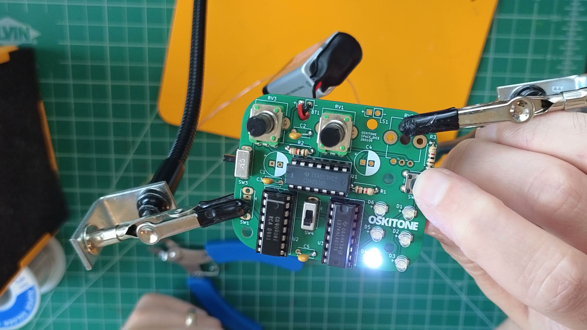
RV1 is an important part of the circuit but, for now, turning it has no effect.
Not working as expected? Check the PCB troubleshooting section. Otherwise, continue.
How it works

- R1 and RV2 are wired serially as a pull-down resistor to the oscillator's control input.
- When the SW2 is closed, VCC tells the oscillator to run; when it's open, the pulldown brings it back down low to 0v.
- C3 and C5 are bypass/decoupling capacitors. Their job is to prevent spurious noise in the supply voltage from affecting the circuit's performance.
- RV1 indeed does nothing, yet!
You've made a kind of random number generator! Depending on how fast the oscillator is running and how long you have it cycle, which LED it lights can be effectively impossible to predict. This is similar to how mechanical game spinners work.
Consider:
- A potentiometer is also called a variable resistor. Its resistance is anywhere between 0 and its prescribed value, based on how it's set.
- When resistors are connected one after the other, this is called "serial." Their total resistance is the sum of their values.
- Knowing this, why doesn't turning RV1 have any effect?
- R2 and RV3 are also wired serially, and turning RV3 does indeed have an effect. What's different? And how would it behave if R2 weren't there?
- When would you consider the output to not be random?