Lights on
Work in Progress
These docs are still a work-in-progress and may not be fully baked just yet! Please contact me if any of it seems very wrong or needs extra clarification.
info
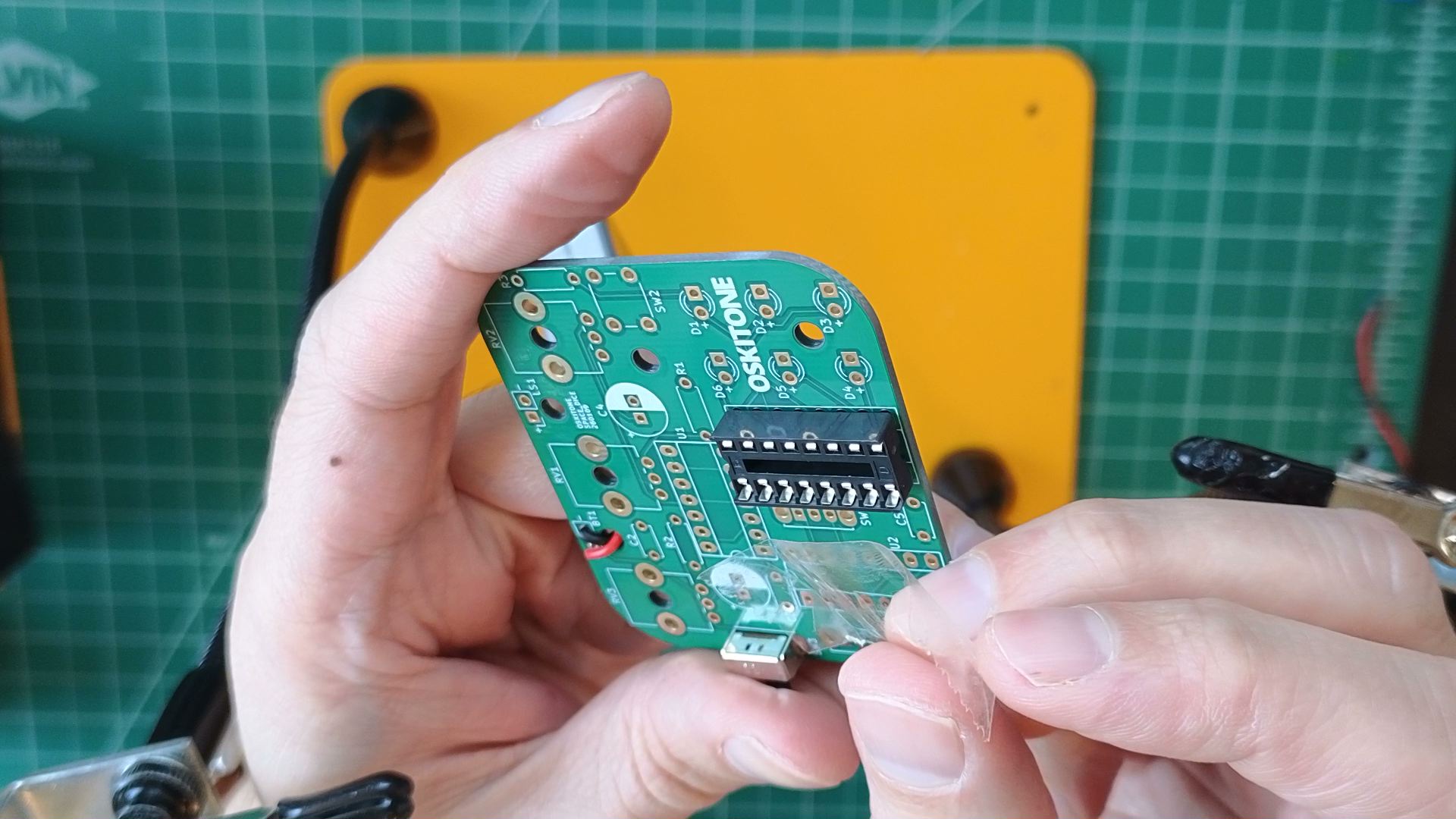
There are three sockets in this kit: one with 14 pins (7 on each side) and two with 16 (8 on each side). For this step, we want a 16-pin one.
Steps
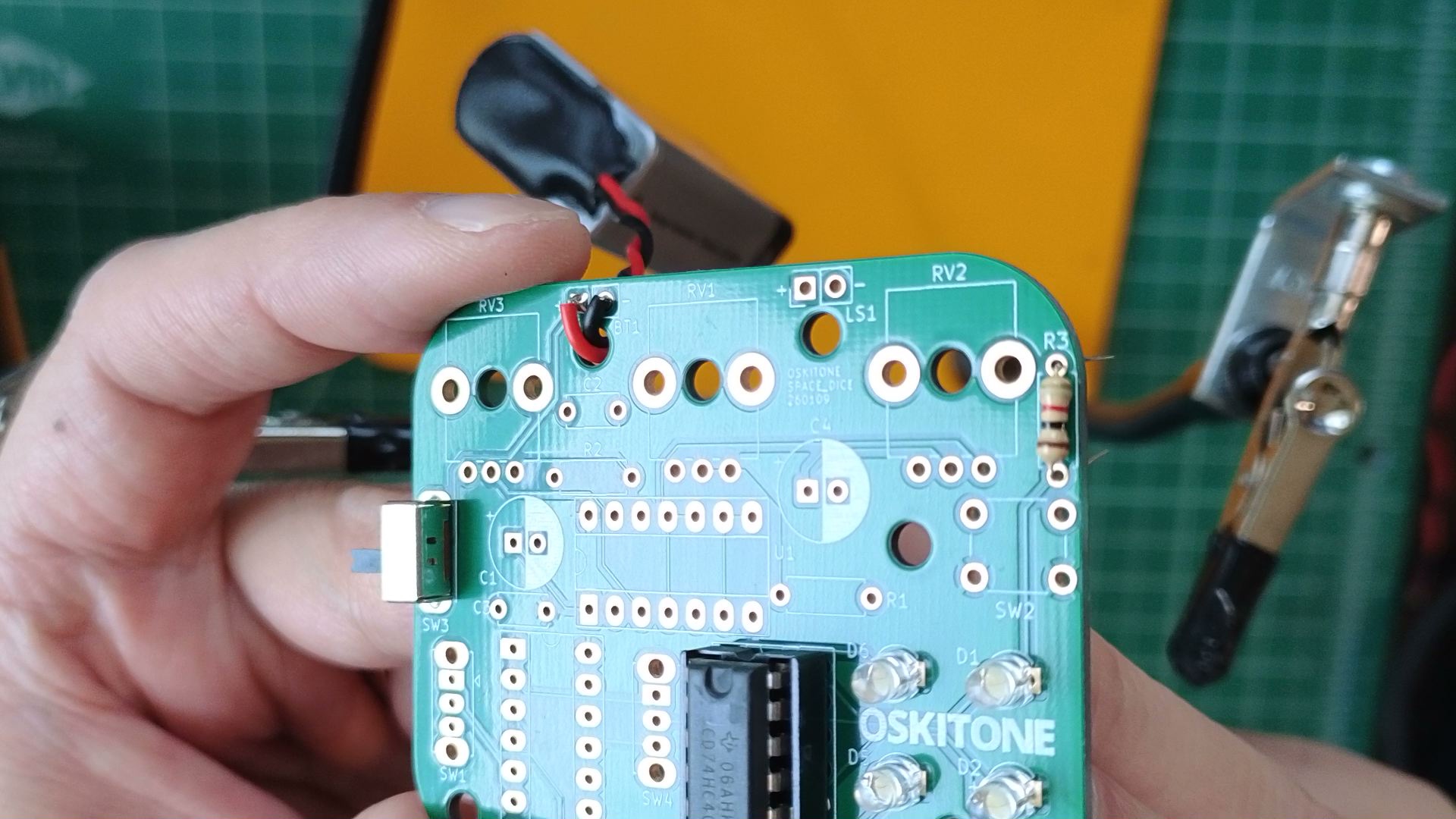
- Solder U3 chip socket
- Find the 16-pin socket to U3. It will have a dimple or notch at one end, which will match the footprint on the PCB.
- To hold it in place, tape it on top and then solder a pin on each row from the bottom. Then push the socket in while melting the solder.
- Before soldering the rest of the pins, verify the socket is perfectly flat against the PCB. If it's not, push the socket into the PCB while remelting the applied solder. (If it's not flat and you try pushing it in, you can accidentally pop out a pin — not good!)
- When it's good and flat, solder the remaining pins.
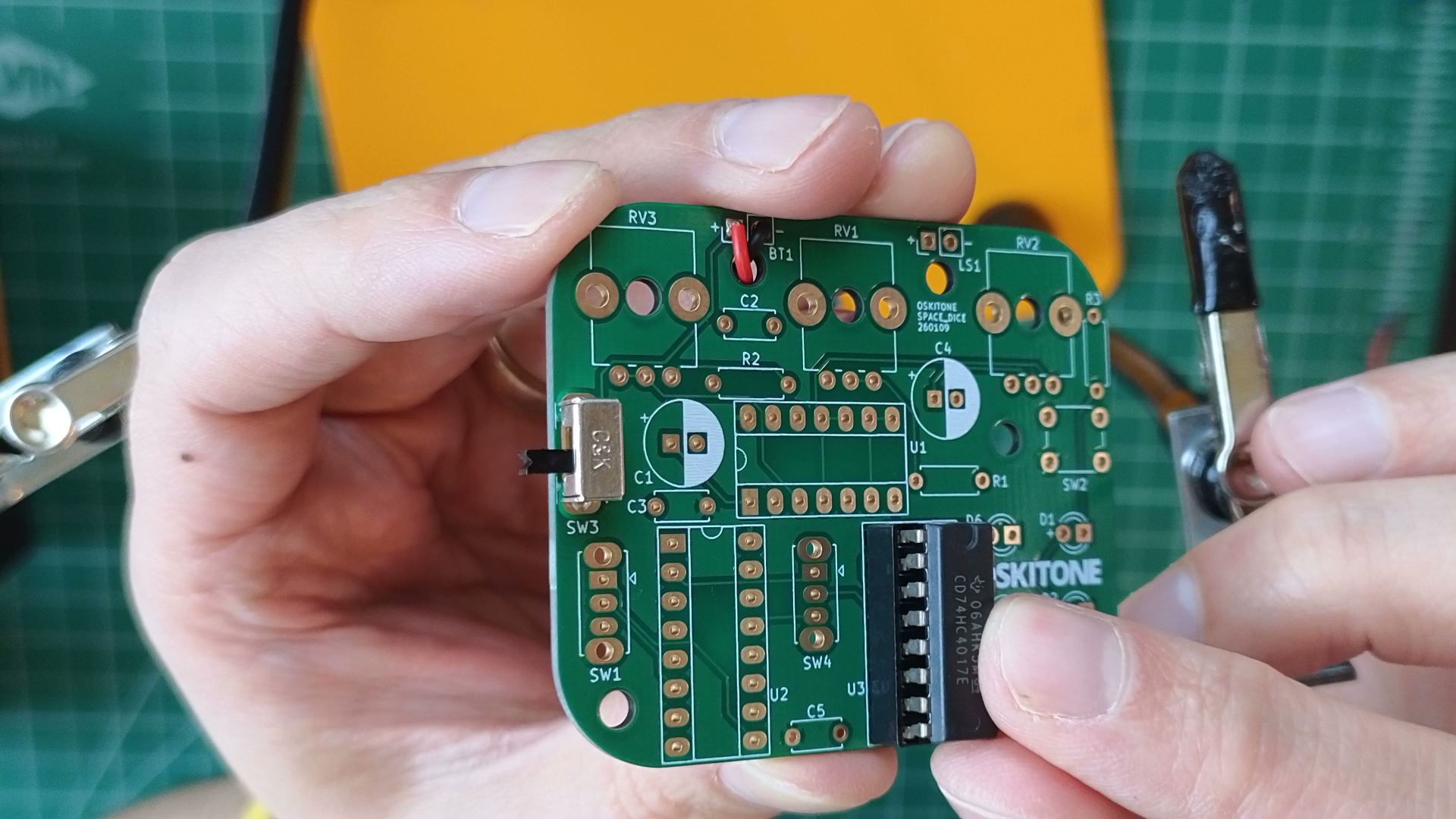
- Insert chip into socket
- If necessary, bend the pins of the 4017 IC chip so that they're straight up and down, not angled.
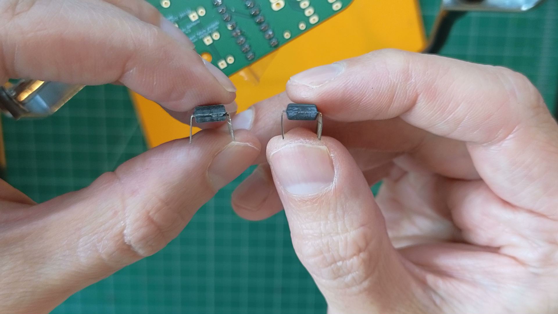
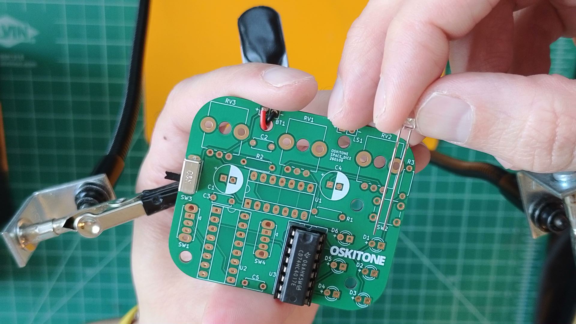
- Match the 4017 chip's dimple to its socket, then push it all the way in.

- If necessary, bend the pins of the 4017 IC chip so that they're straight up and down, not angled.
- Solder LEDs
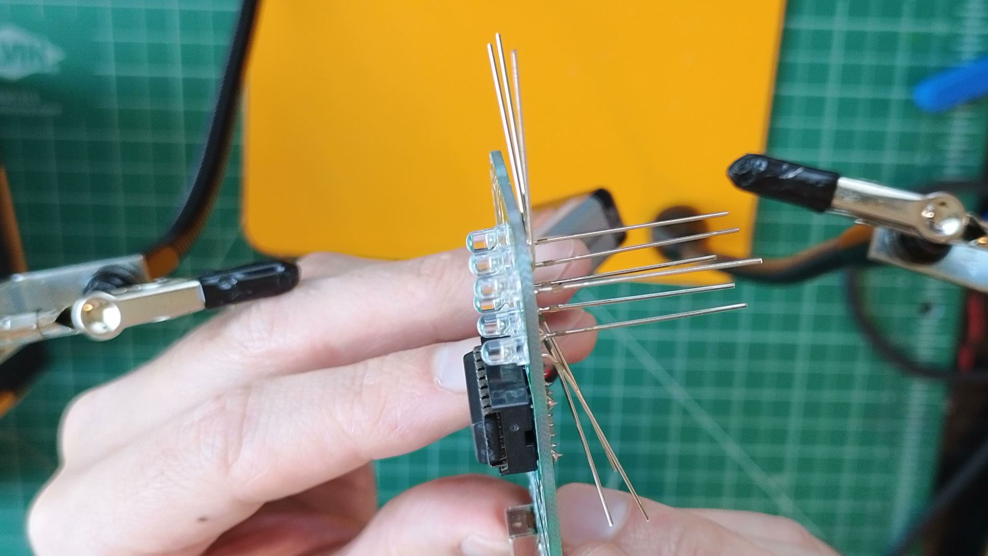
- Note the small "+" signs beside D1 through D6. LEDs have polarity and won't work if connected backwards. Insert each LED so its long leg is in the "+" hole.
- Solder one leg of each LED and make sure they're all lined up and flat against the PCB before soldering their other legs.
- Note the small "+" signs beside D1 through D6. LEDs have polarity and won't work if connected backwards. Insert each LED so its long leg is in the "+" hole.
- Solder a 1k (Brown Black Red) resistor to R3.


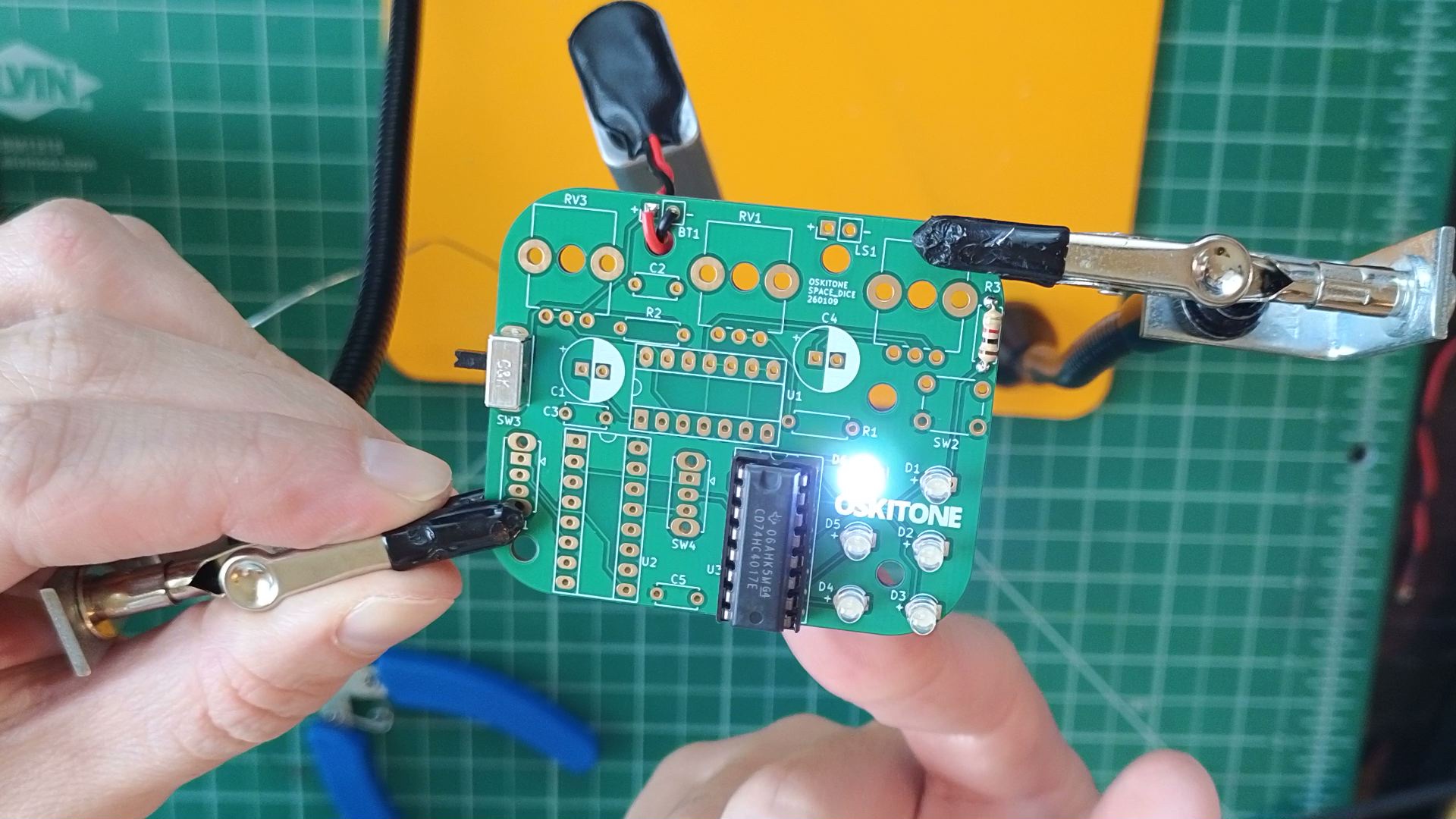
Test
Powering the board should light up one of the LEDs. If not, try running a finger across the soldered pins of U3. That should change which one is lit.
info
The lit LED may not match the one in the photo. It may also seem like some LEDs are not lighting at all. Both situations are fine for now.
Not working as expected? It's probably a polarity issue. Confirm that the chip and LEDs are all inserted in the right orientation, then check the PCB troubleshooting section. Otherwise, continue.
How it works

- The 4017 is a decade counter. Its job is to count pulses of high voltage at its CLK input, then display that number on one of its ten outputs. After the tenth output is high or when its RESET input is pulsed, it resets to the first output.
- Check out its schematic layout. In real life, chips' pins are in neat rows, ordered counter-clockwise. In schematics, their pins are usually arranged by function: inputs and outputs on opposite sides, power at top and bottom, and pins ordered to match their uses.
- CKEN is "ClocK ENable" and is brought low to GND for regular operation. You might expect us to bring it high to enable the clock, but that's not always the case.
- CLK is unconnected. A "floating" input!
- The 4017 is called a decade counter because it has ten ("dec") outputs. It counts in base 10, AKA decimal.
- R3 limits the current to the LED so it doesn't burn out. The schematic denotes a suitable range of 330ohm (very bright, minimum to not burn out LED) to 1k (1000ohm, dimmer, what's included in the kit).
Consider
- Sometimes, when powering up the board, no LEDs are lit. Why?
- Why do you think touching the chip's pins with your finger changes its output?