Pew pew pew
Work in Progress
These docs are still a work-in-progress and may not be fully baked just yet! Please contact me if any of it seems very wrong or needs extra clarification.
This is a simple one!
Step(s)
- Solder 220uF capacitor to C1. As always, note polarity.
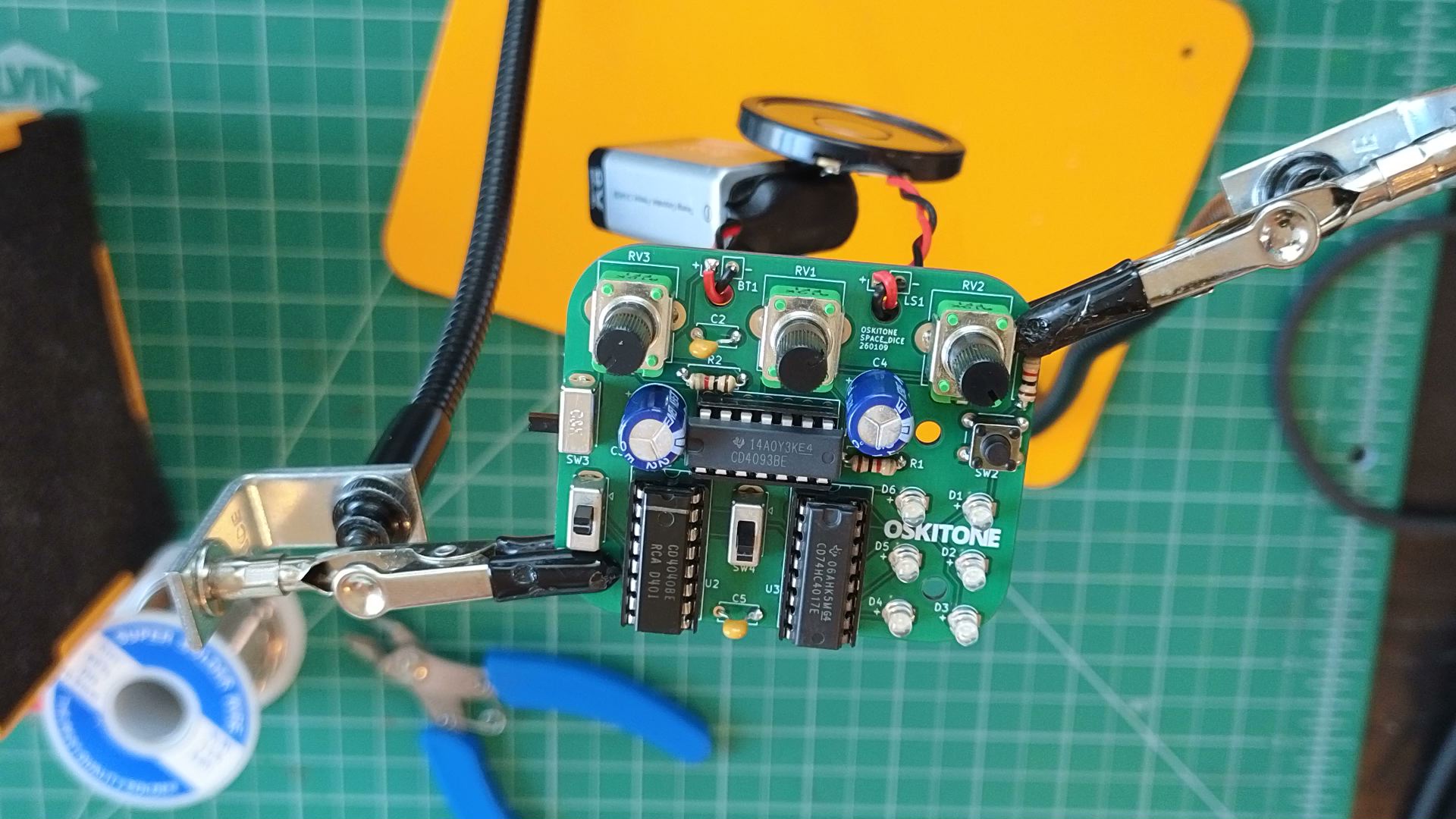
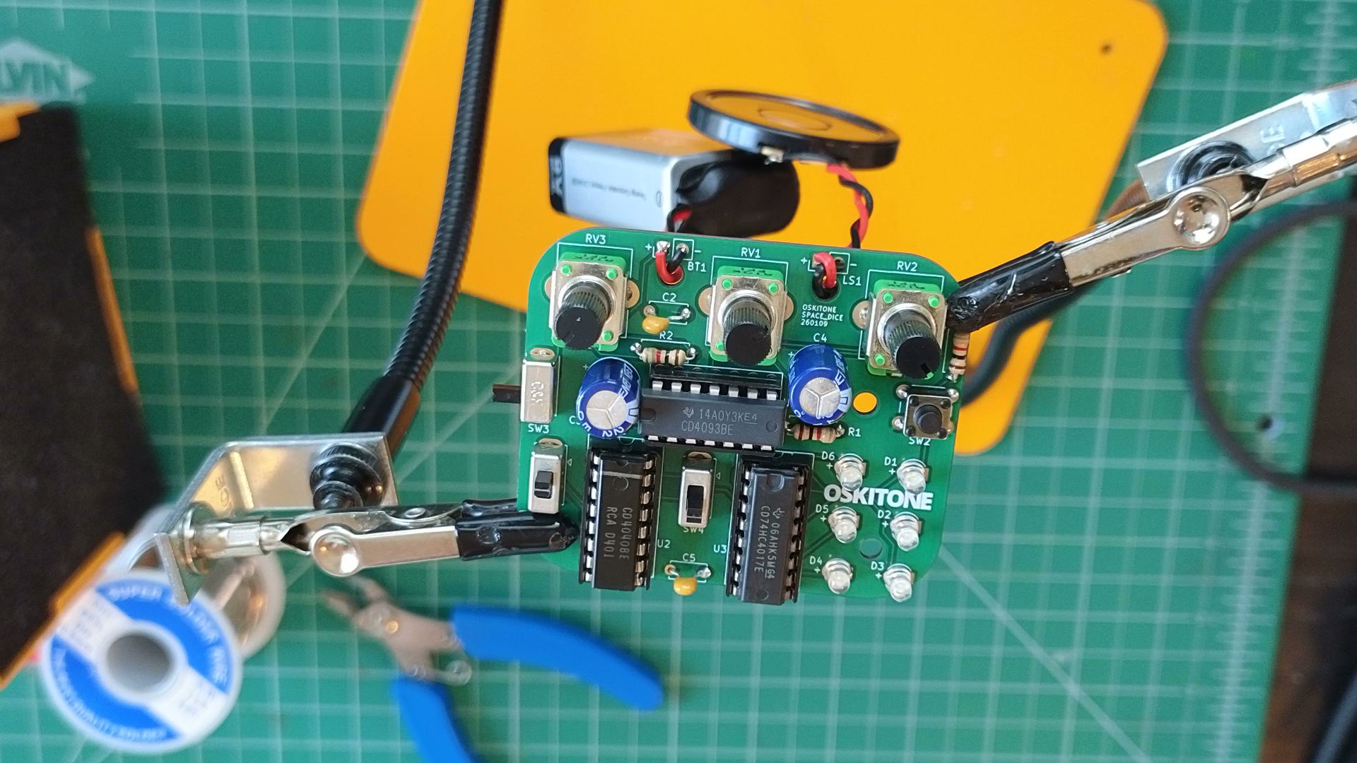
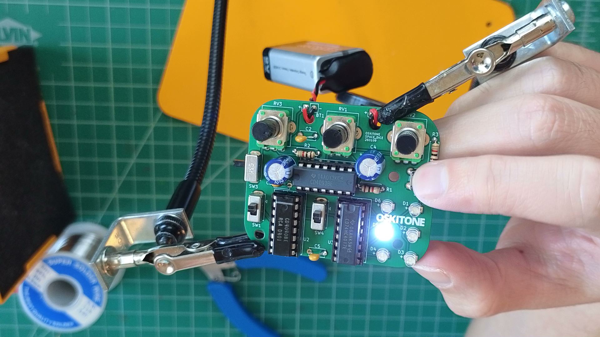
Test
The beep from before should now drop down in frequency after it starts. Does it sound like a little space laser? RV1 controls its rate of decay.
Not working as expected? Check the PCB troubleshooting section. Otherwise, continue.
How it works
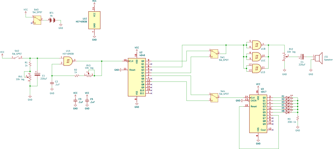
- C1 stores voltage from VCC to the oscillator's control input, extending how long the oscillator runs beyond SW2's closure.
- However, we still have the R1+RV1 pull-down from before. It now drains the cap's voltage to GND, so the oscillator can't run forever.
- The previously useless RV1 pot is now very useful. It controls the speed of that voltage drain.
- Surprisingly, when the input voltage drops low, the oscillator frequency goes low too. The result is a distinct "laser" sound that starts at a high frequency and then drops low before ending. This is a hack!
- Logic gates are digital machines. Their inputs and outputs are binary, either high or low. When treated this way, their behavior is as expected. They are in specification, in-spec.
- If you give them some voltage that's in the middle of VCC and GND, like 3 or 4 volts from the battery's 9v, that is out-of-spec. Manufacturers warn about out-of-spec usages because they can't guarantee how the chip will react. The frequency drop here is almost certainly an unexpected, out-of-spec behavior.
- Is it good for the chip to be run out-of-spec? Probably not! But it doesn't seem to do it any harm in these short bursts.
- The enclosure labels RV1 "DROP." Like time to drop? "DECAY" would have been preferable but didn't fit!
Consider:
- What do you think would happen if we had C1 but without its sibling pulldown/drain resistors?
- If you have a fast enough multimeter, you could measure the draining voltage at pin 1 of U1A. How does it compare to the frequency drop?
PCB done!
You're all done soldering the PCB. Turn off your soldering iron and go wash your hands.
If you're up to it, take a minute to read the full, annotated Space Dice schematic. Does it make sense?
Next you'll be putting it together with the 3D-printed parts.