Power up
The SPST switch has very short legs and won't stay in the PCB, making it tricky to solder. You can use a bit of tape to hold it in place as you solder. See the general tips section for other advice.
Steps
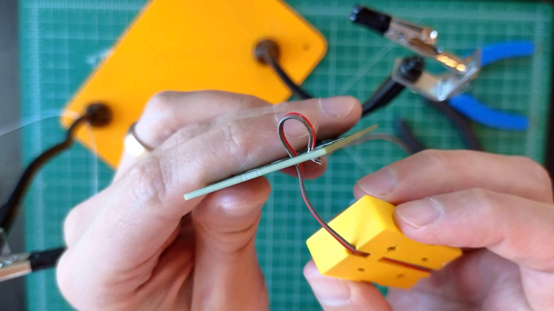
- Wire battery pack to BT1
- Thread the loose end of the ribbon cable connected to the battery pack up through the hole near BT1.

- Strip its wires and solder in place. Make sure the "+" and "-" wires are going to the right places.
- Thread the loose end of the ribbon cable connected to the battery pack up through the hole near BT1.
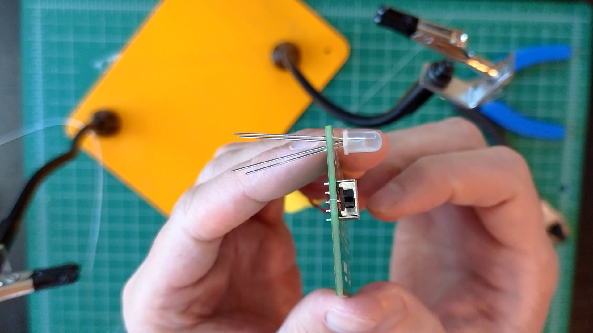
- Solder RGB LED at D1
- The LED has four pins for three different colors plus ground. The longest one is to ground and it goes to the hole that has a line coming out of it.

- Push the LED into the PCB as far as you can; it doesn't have to be flat against the PCB but does need to be straight up and down — no leaning!
- The LED has four pins for three different colors plus ground. The longest one is to ground and it goes to the hole that has a line coming out of it.
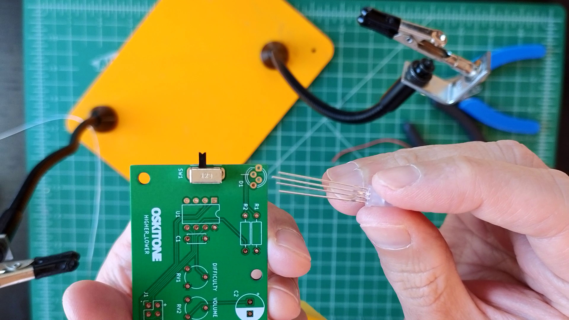
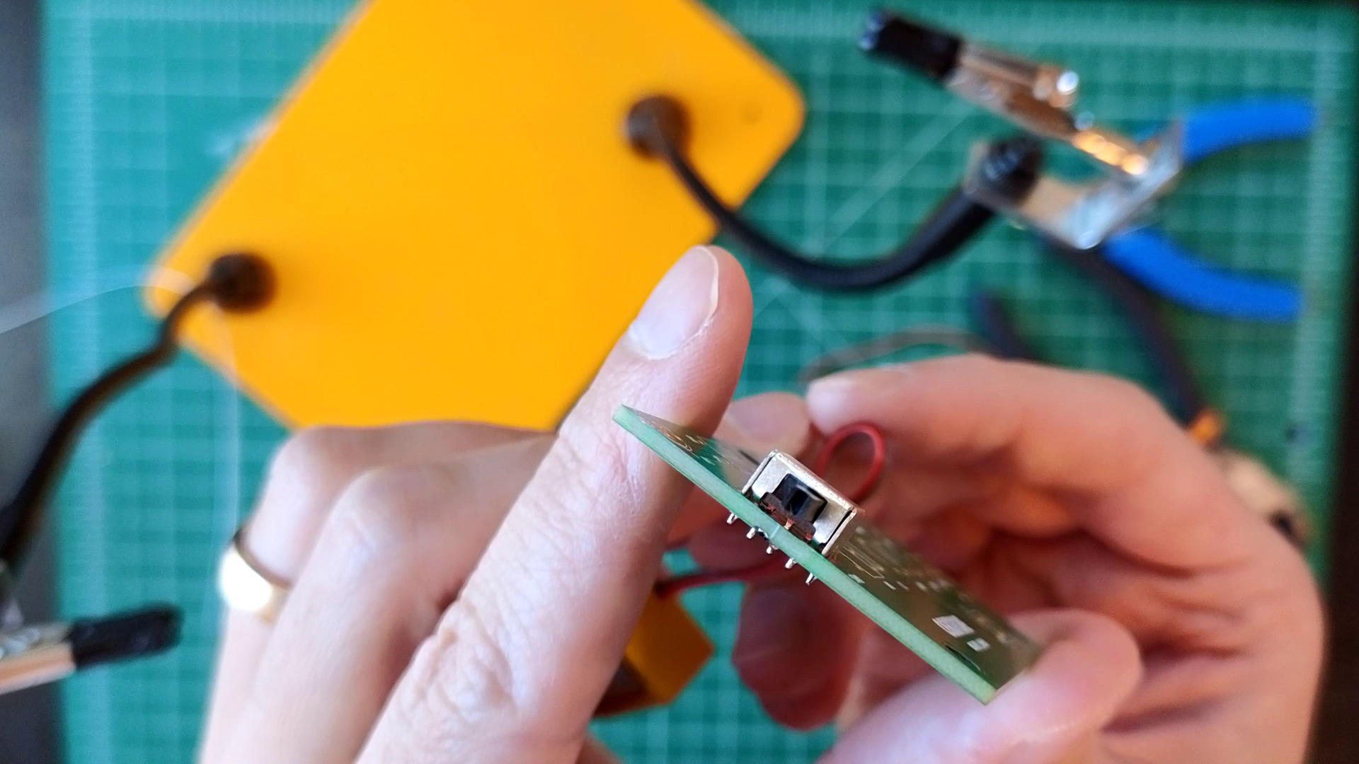
- Solder sliding toggle switch SW1 and resistor R1 (1k, Brown Black Red).
- Make sure the switch is flat against the PCB and its actuator is pointing left, away from the PCB.

- Make sure the switch is flat against the PCB and its actuator is pointing left, away from the PCB.
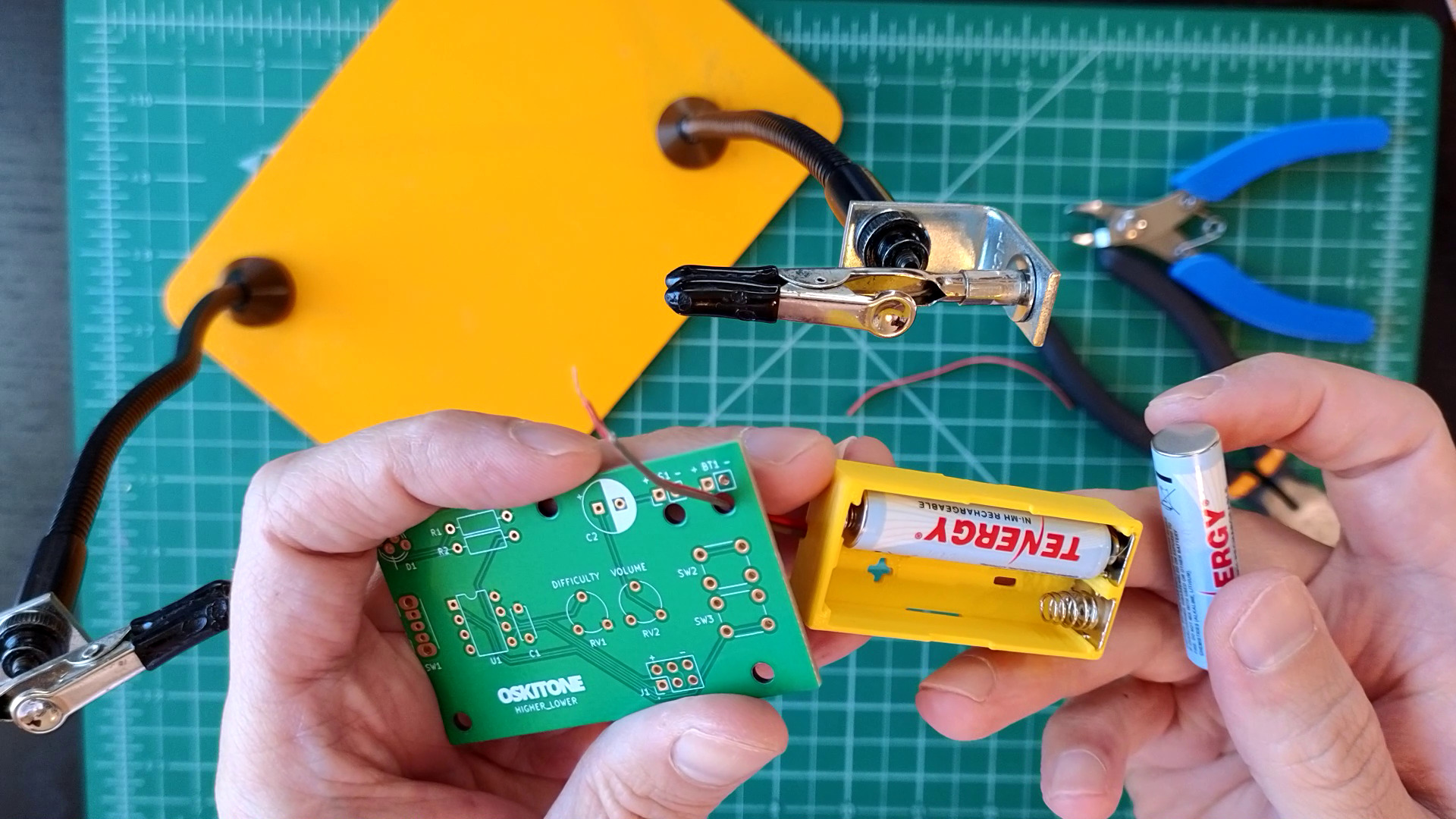


Test
Add the batteries back into the battery holder. Toggling SW1 should now light one color of the LED! Power off before continuing soldering.
Not working as expected? Check the PCB troubleshooting section. Otherwise, continue.
How it works
An RGB LED is a Light-Emitting Diode with three pins for the colors Red, Green, and Blue.
This RGB LED is common cathode, so the longest pin goes to ground (the "-" side of the battery). The other kind of RGB LED is common anode, where the longest pin goes high to voltage (the "+" side of the battery).
LEDs can burn out if they're supplied too much electricity. While there's not much risk of that with just the two AAA batteries, the resistor at R1 limits the current supplied to prevent burnout and, more importantly, make sure the LED doesn't shine too bright.
Toggling SW1 completes the circuit so that electricity can flow from the battery, through the resistor, to the LED, and finally back into the battery.