Make some noise
Steps
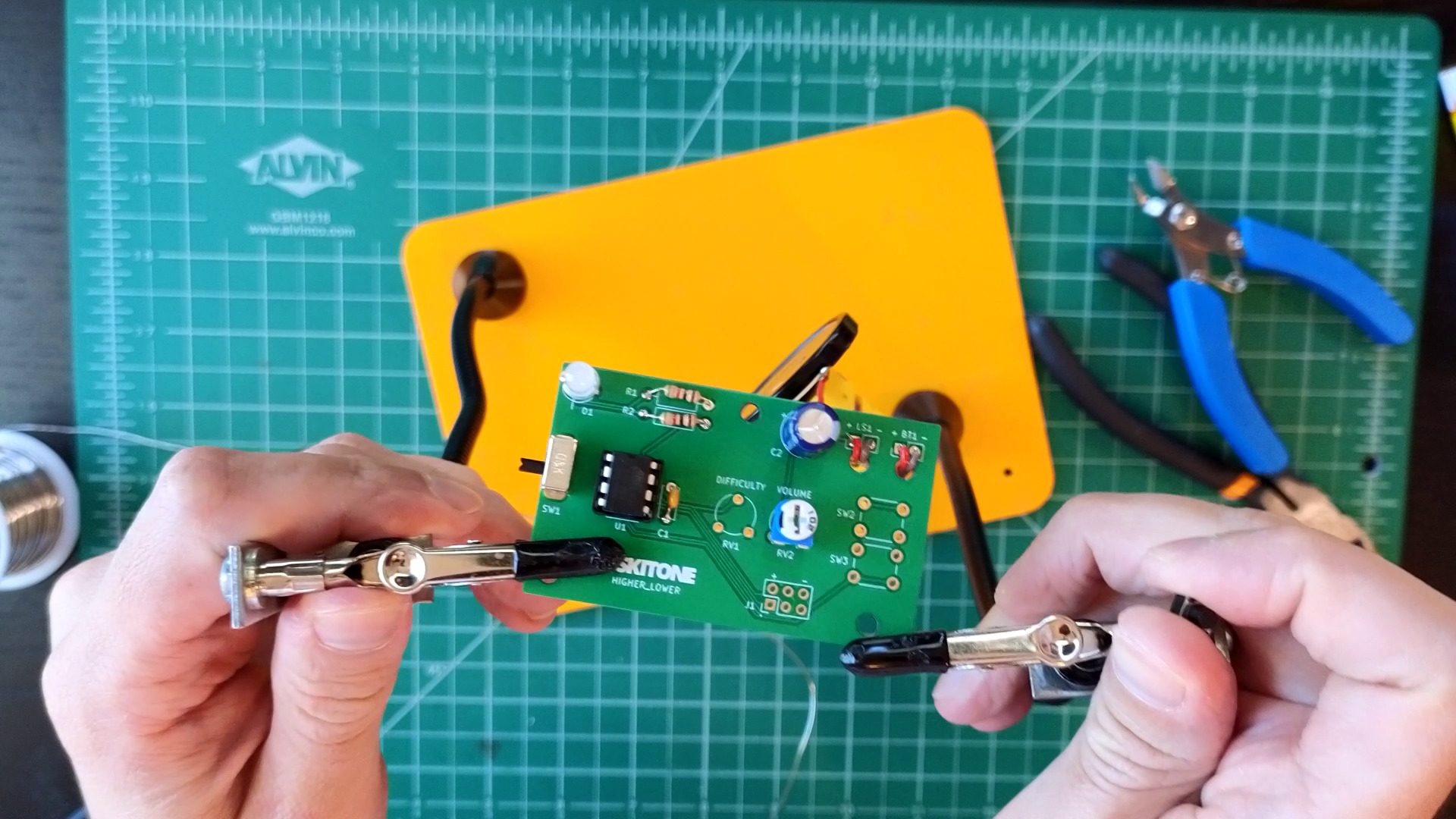
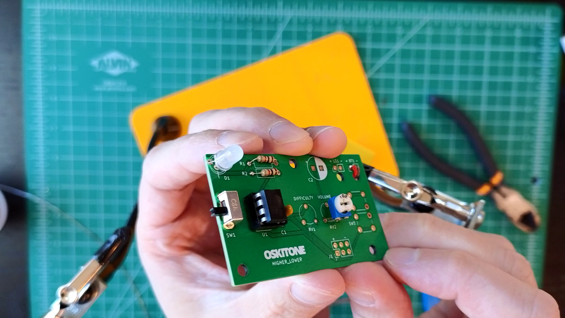
- Solder trim potentiometer (aka "trimpot") RV2 (1k, marked "102").
- Make sure RV2 is pushed all the way into PCB before soldering all of its pins.

- Make sure RV2 is pushed all the way into PCB before soldering all of its pins.
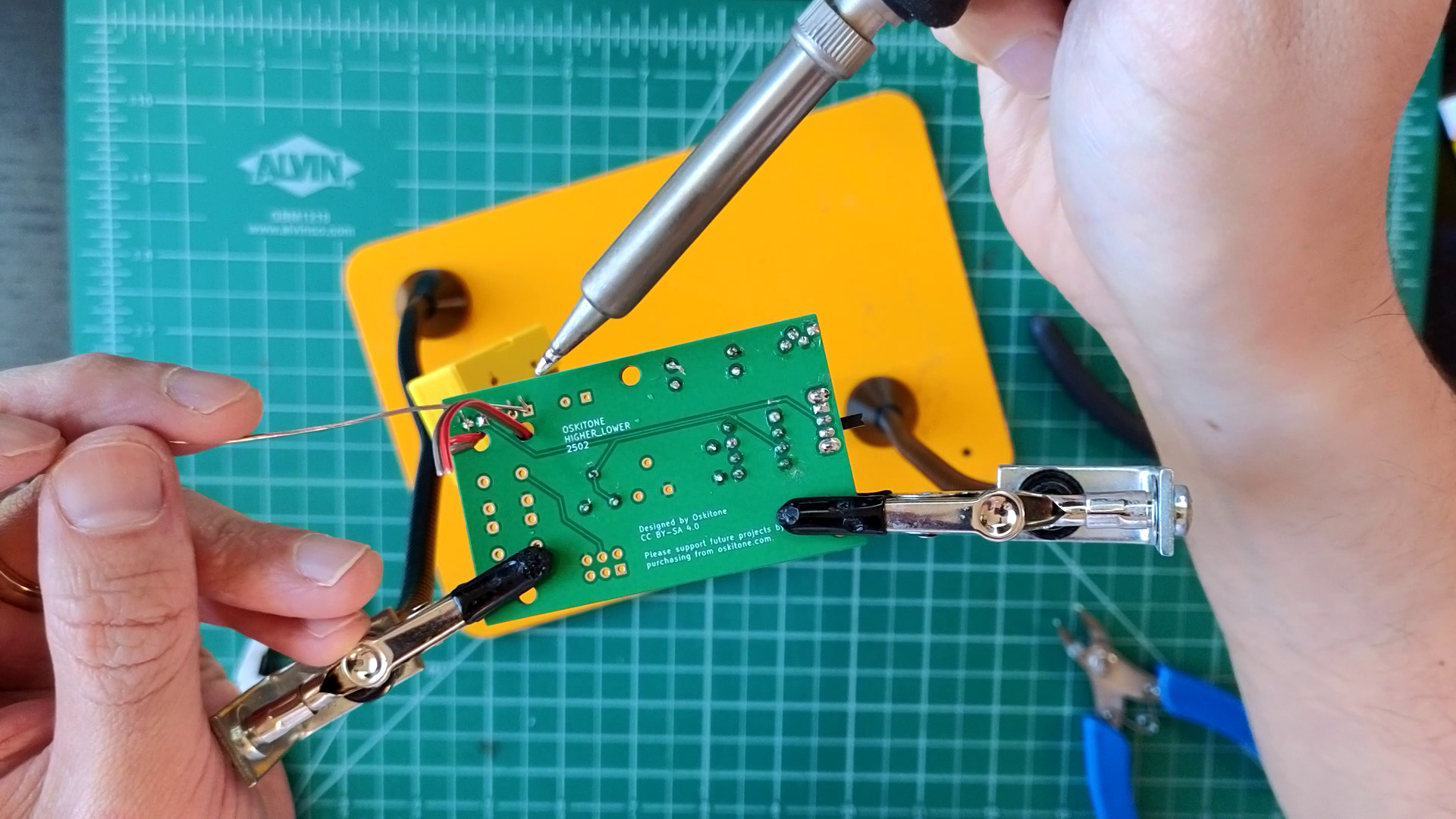
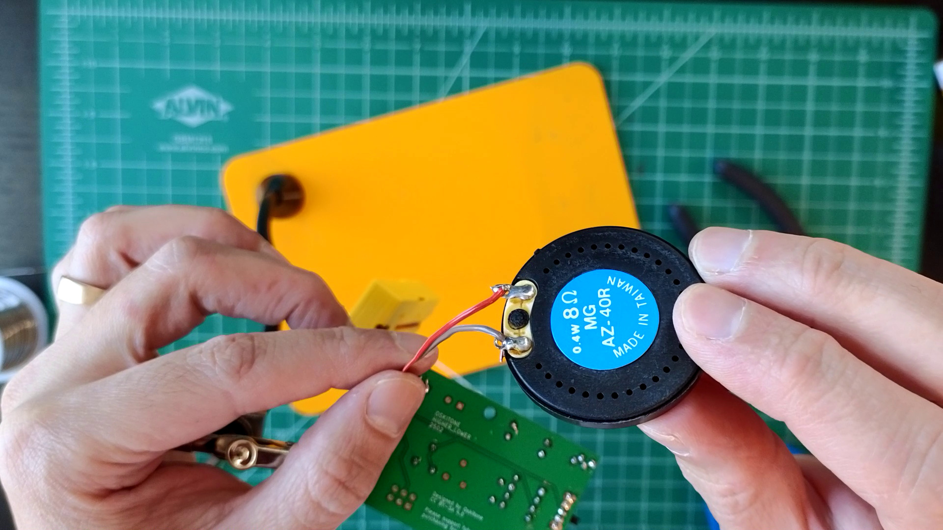
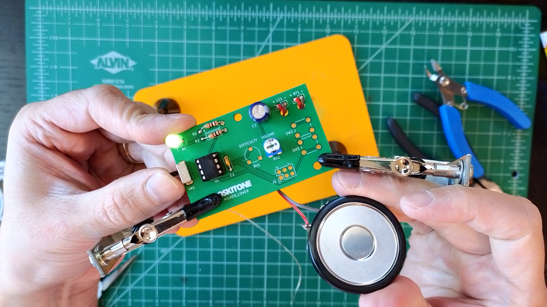
- Wire speaker to LS1.
- Thread remaining piece of ribbon cable through the hole by LS1.
- Separate wires and strip 1/4" of insulation, then solder to LS1.
- Strip and solder the other ends to the speaker, matching the "+" and "-" sides.

- Solder capacitor C2 (220uF).
- C2 has polarity. Match its white side to the white side of its footprint.
- C2 has polarity. Match its white side to the white side of its footprint.


Test
Sliding SW1 to power the board, a little tune plays out of the speaker. This is the "Higher Lower" game theme song!
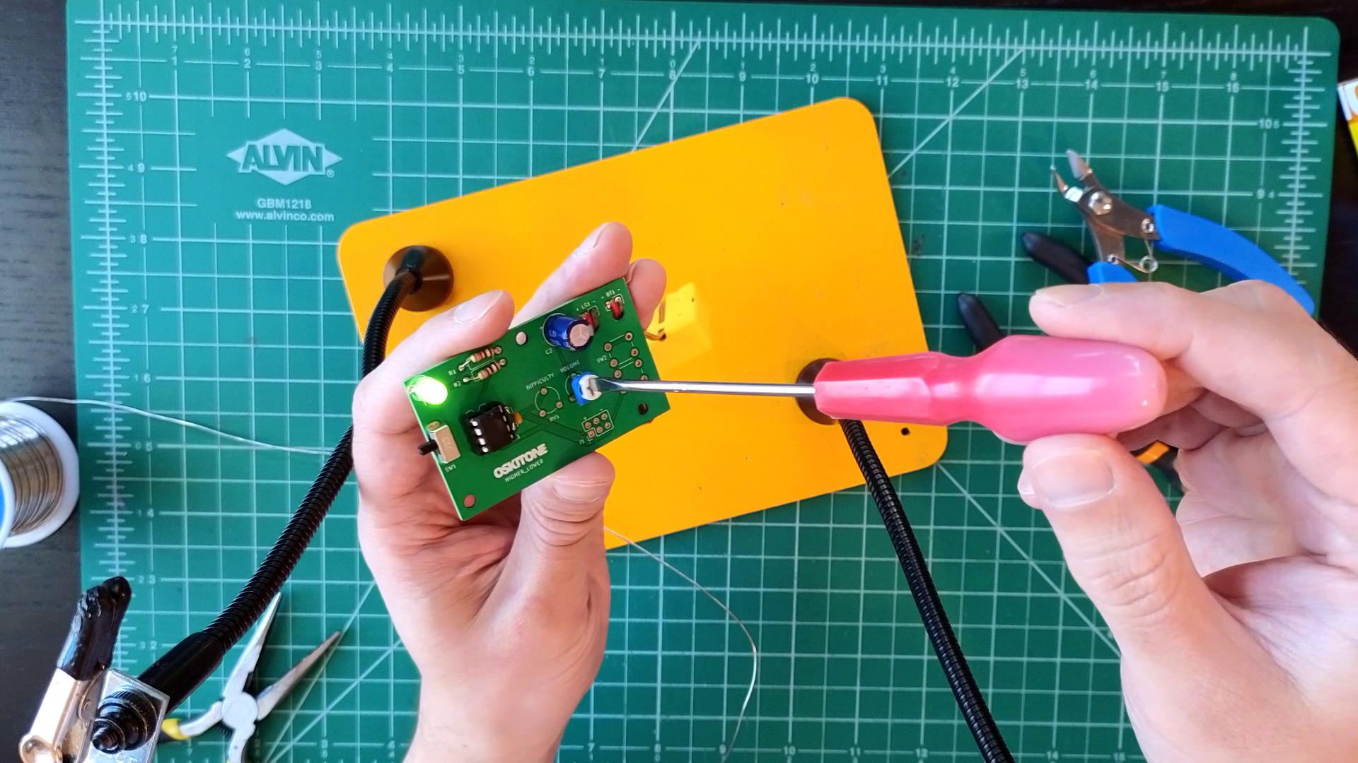
Adjust RV2 with a screwdriver for volume control.
Not working as expected? Check the PCB troubleshooting section. Otherwise, continue.
How it works
One of the pins on the ATtiny85 is tasked with outputting square waves by quickly alternating between low and high voltage.
It connects to variable resistor RV2, which works the same way that the R1 resistor did when you lit the LED: it limits current. The variable part of RV2 means that how much it limits is set by turning its dial. A higher resistance (measured in Ω or "ohms") means a smaller current which means a quieter sound from the speaker.
Variable resistors are called potentiometers (or "pots"), and small potentiometers like these are trimmers (or, adorably, "trimpots").
C2 is a coupling capacitor. Think of it like a big bucket that fills up with voltage before dumping it at the speaker.
When that voltage drives an electromagnet that vibrates a cone inside the speaker, it creates ripples in the air that eventually reach your ears as sound waves.