Add game inputs
Take your time and make sure the switches are perfectly flat against the PCB before soldering all of their pins.
Step(s)
- Solder SPST switches to SW2 and SW3.
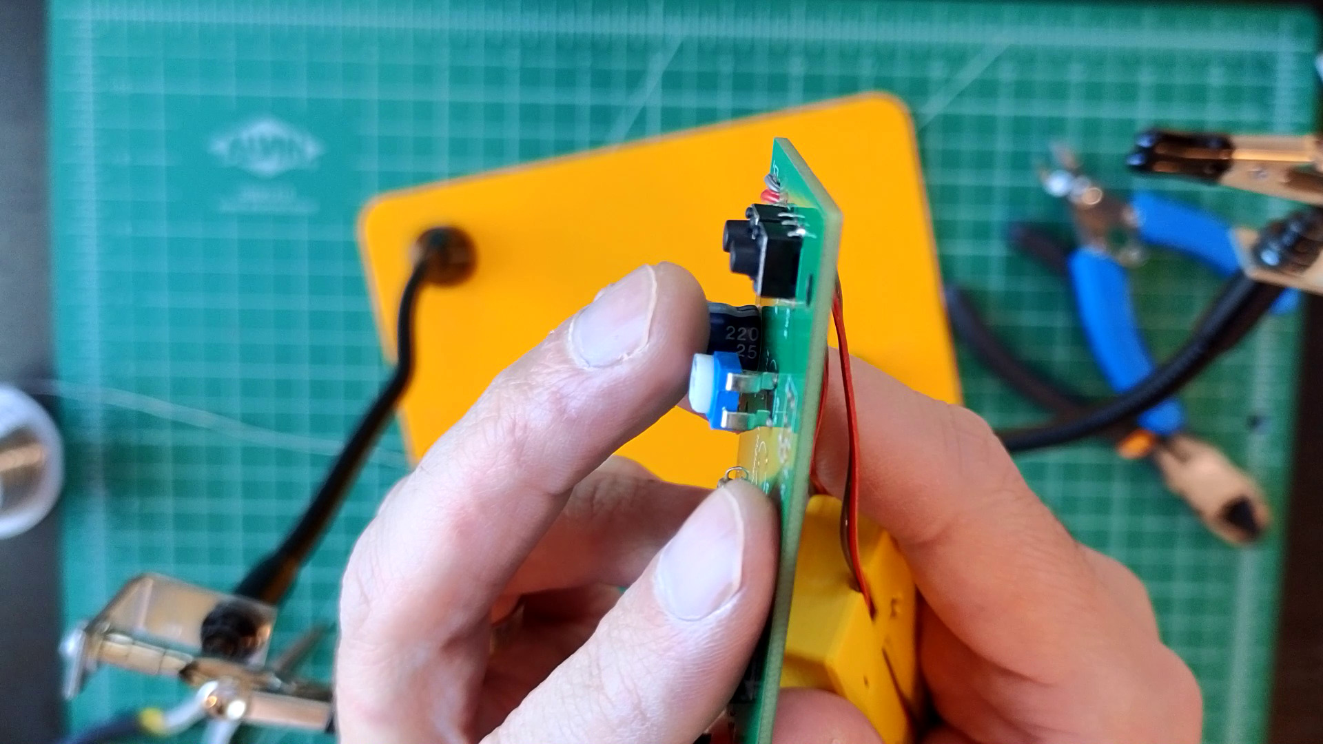 Make sure they're absolutely flat against the PCB before soldering all of their pins.

Test
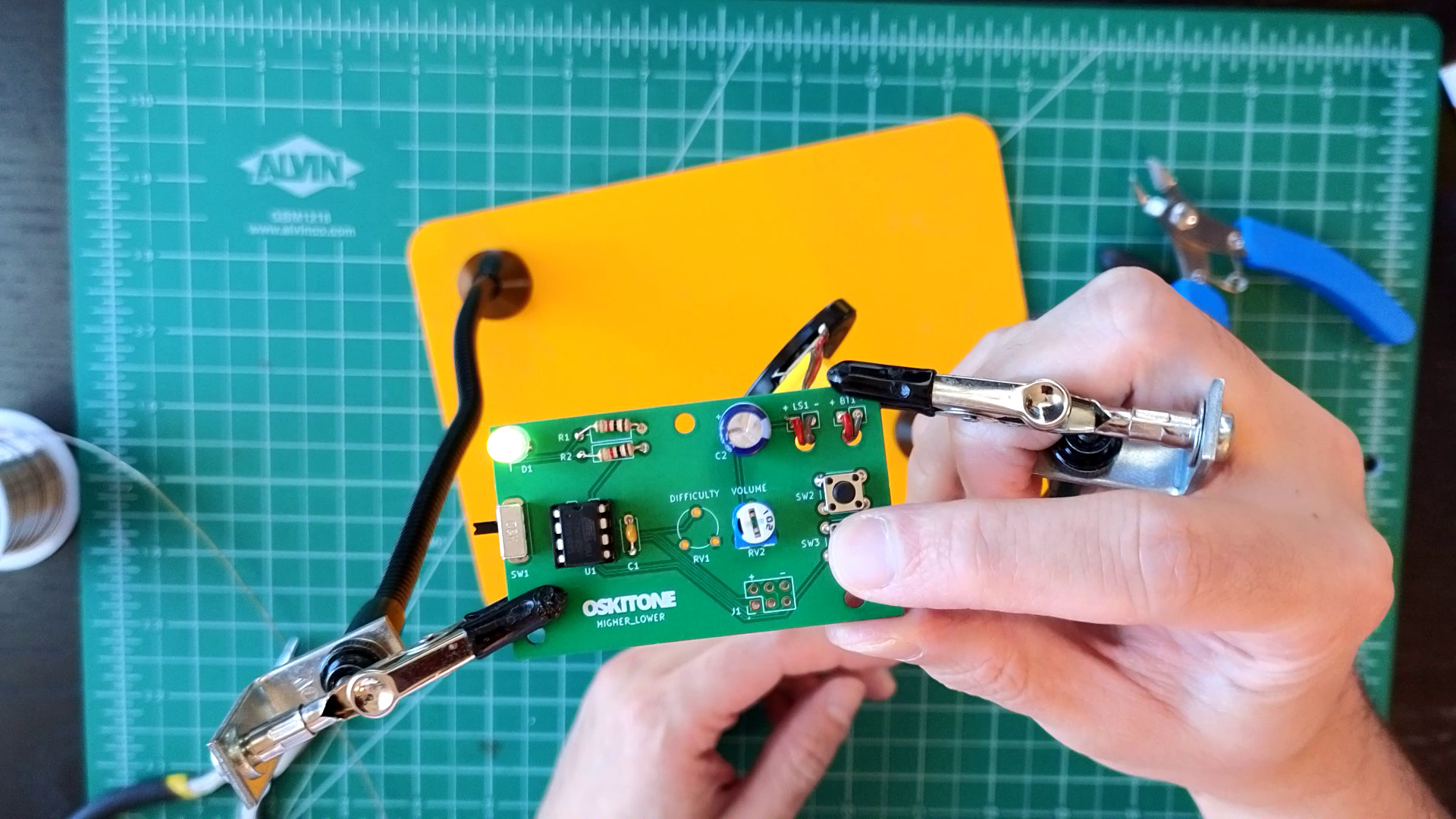
With board powered, pressing either SW2 or SW3 plays more tones out of the speaker and flashes D1.
Not working as expected? Check the PCB troubleshooting section. Otherwise, continue.
How it works
These kinds of switches are SPST, or Single-Pole Single-Throw. Despite having four pins, they're about as simple as a switch can be. When pressed, an internal connection is closed; when it's not pressed, it's open. Both sides of that connection have two pins, so there're four pins total.
SW2 and SW3 connect to two input pins on the ATtiny85.
The inputs are "held high" by the microcontroller, meaning that there's a small current of positive voltage on them. But pressing a switch instead brings them low to ground, and that voltage change can be interpreted by the ATtiny85 as a button press. Pretty cool!