General tips and getting started
Take your time and be patient! If you run into a problem, try to keep a cool head and refer to the PCB troubleshooting section. If your problem remains unfixed and you can't figure it out, please email me to let me know! I'll do my best to help you, and your feedback will help improve the guide and other future Oskitone designs.
General tips
- Component colors
This guide's components' brands and body colors (and even the PCB color itself) may look different from yours, and that's okay! What's important is that the part types and values are in the right spots. - Resistors are labeled with colors, capacitors with numbers
Resistors' values are marked as colored bands on their body. Ceramic capacitors use a number system to denote their value. - Ceramic and electrolytic capacitors
There are two kinds of “caps” used in this kit. Ceramic capacitors are small, circular, and have no polarity; they can be placed in either direction. Electrolytic caps are bigger, cylindrical, and have marked +/- polarities. - IC chips are static-sensitive
The included IC chips can be damaged by static electricity. Leave them in their packaging until ready to install. Before handling, discharge any static electricity on your body by touching a large piece of metal. You can even use an anti-static mat and/or wrist strap for extra caution. - ICs in sockets
Each IC chip comes with a corresponding socket with the same number of pins. You will solder the socket to the PCB, not the chip itself. This prevents overheating the IC with the soldering iron and makes it easier to switch a faulty one out. - Component polarities
LEDs, batteries, and electrolytic capacitors have positive and negative leads. Where applicable, the PCB will be labeled where each lead goes or a component outline to denote orientation. - IC orientation
The IC chips also have an orientation, marked by a notch at their top. Make sure these line up when soldering the sockets and again when inserting the chips. A chip can be permanently damaged if inserted incorrectly! - Get tricky/sticky with short-lead components
Components with short leads can be hard to get to stay on the PCB, because you can't really bend their leads to get them to stay put. But there are tricks! Try using tape or "Blu-Tack" adhesive to hold them. Or clip the solder into your "holding hands", and try bringing the board to the solder (instead of the typical reverse of solder to board).
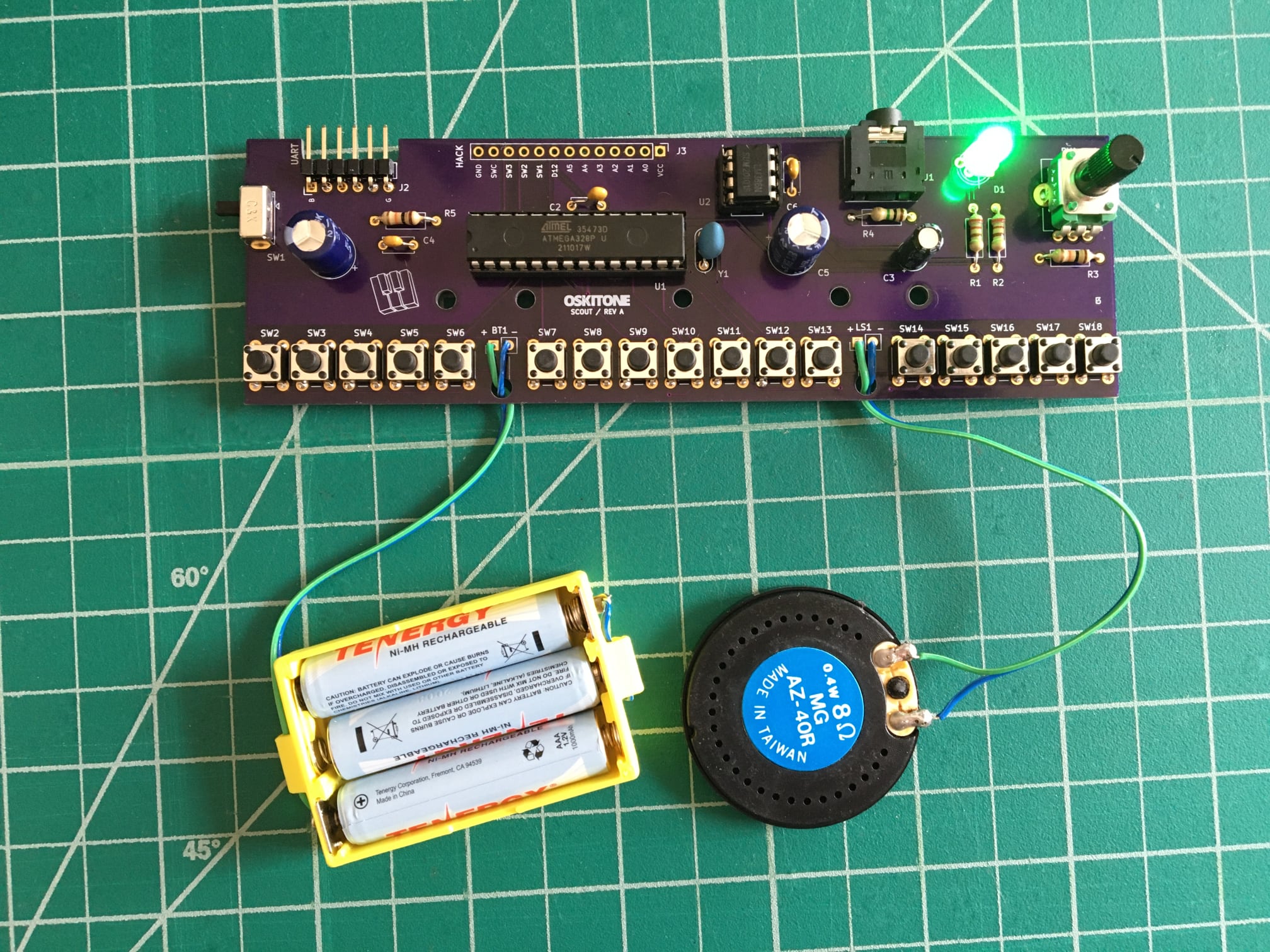
Let's get started!
For reference, we'll end up with something like this when we're done:
How this guide is organized
Each group of steps in the Scout's assembly has a test at the end to make sure everything you just did is working as expected, ie: "Make sure the LED lights up", "Make sure the microcontroller works", "Make sure the speaker has sound", etc.
If it doesn't work, don't fret! Look over the PCB troubleshooting tips. Don't move on in the instructions until you've got the test working.
The guide's steps are intentionally ordered. If you don't want to follow the guide, that's okay! But it may be harder to debug later if anything doesn't work as expected.