Boot the microcontroller
Steps
- Solder capacitors C1 (220uF) and C2 (.1uF, marked 104), oscillator Y1, and resistors R2 (220, Red Red Brown) and R5 (10k, Brown Black Orange).
- C1 has polarity. Match its white side to the white side of its footprint.
- Y1 has three legs and no polarity.
- Solder U1 socket. It will have a dimple at one end, which should match the footprint on the PCB.
- Solder two pins on opposite sides and verify the socket is perfectly flat before soldering the rest. If it's not and you try pushing it in, you can accidentally pop out a pin — not good!
- With the power off, carefully insert ATmega328. It will have a dimple (and/or a small dot in a corner), which should match the socket.
Test
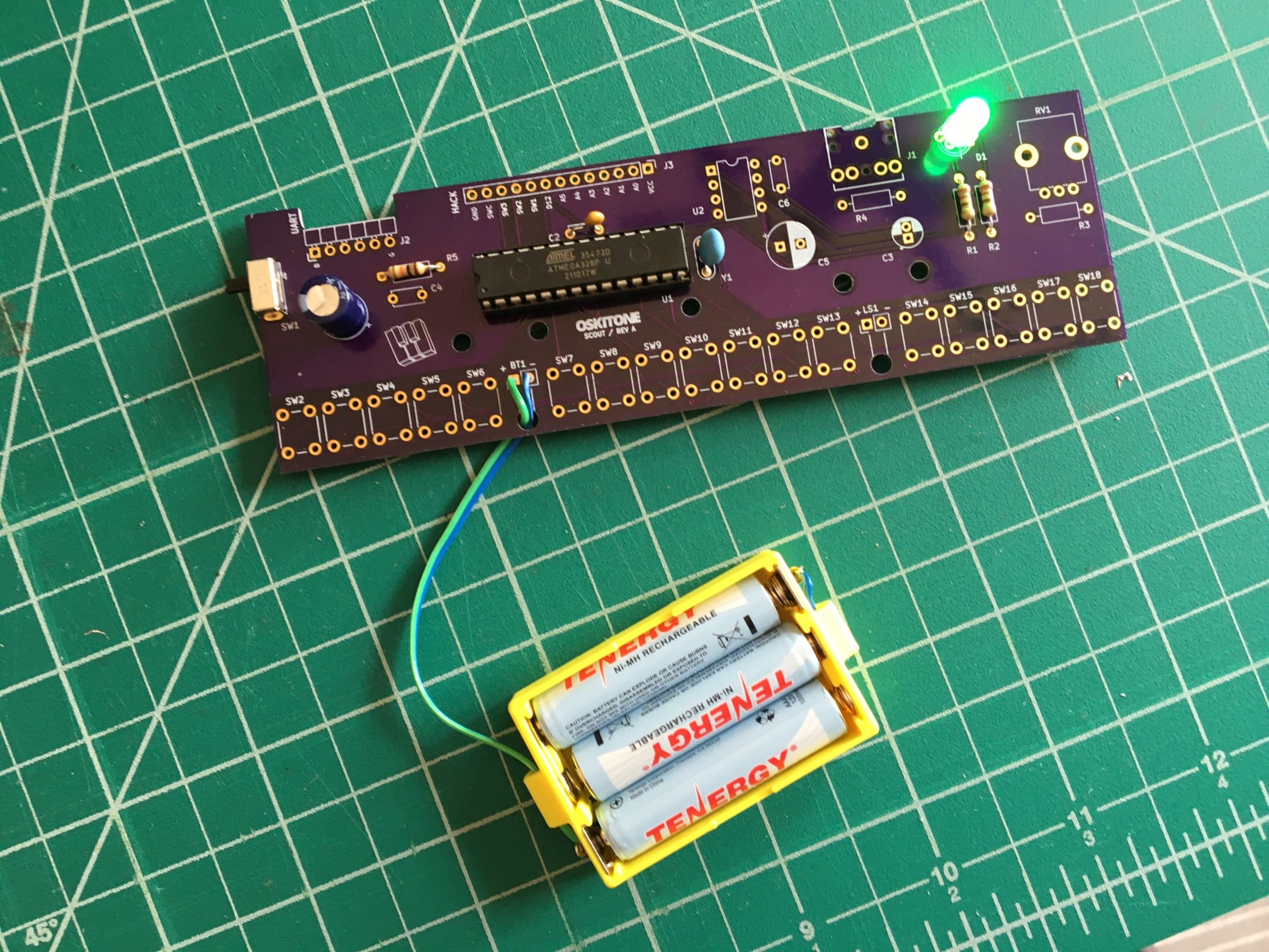
Turn the power switch back on, and the LED should blink a new, different color a couple times. This lets you know that the ATmega is booted up and ready. Power off.
Not working as expected? Check the PCB troubleshooting section. Otherwise, continue to the next step.