Power up
Steps
- Solder LED at D1
- The LED has four pins for three different colors plus ground. The longest one is to ground and it goes to the hole that has a line coming out of it.
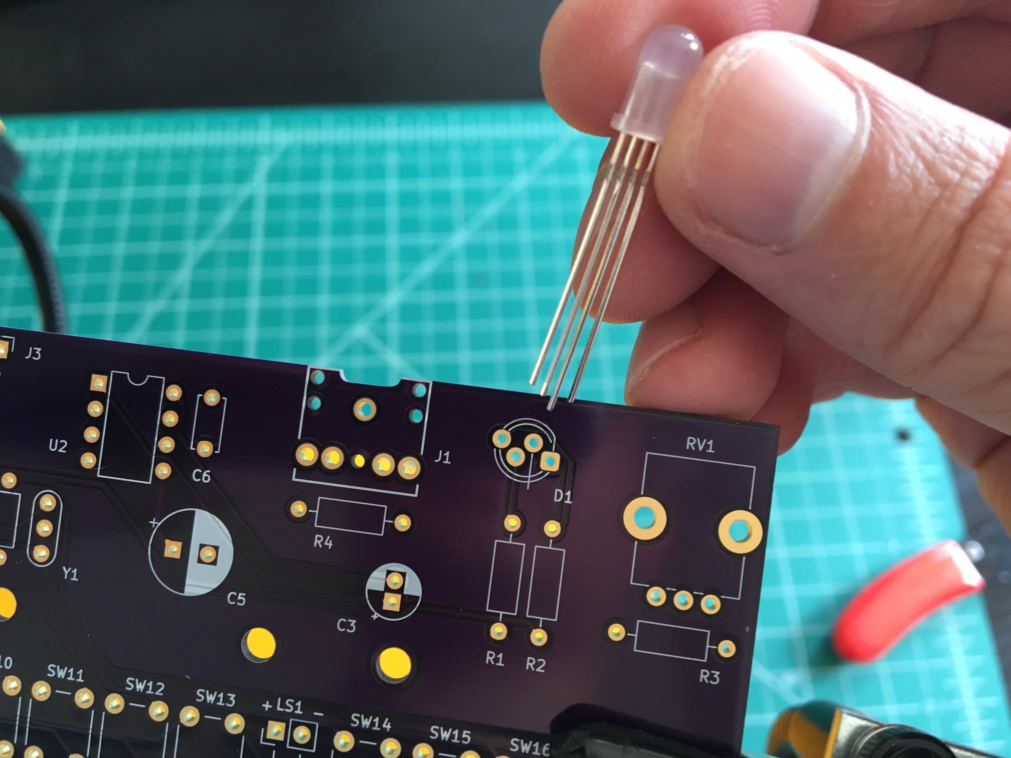
- Get the LED as vertically close to the PCB as reasonable; it doesn't have to be flat against PCB but does need to be straight up and down -- no leaning!
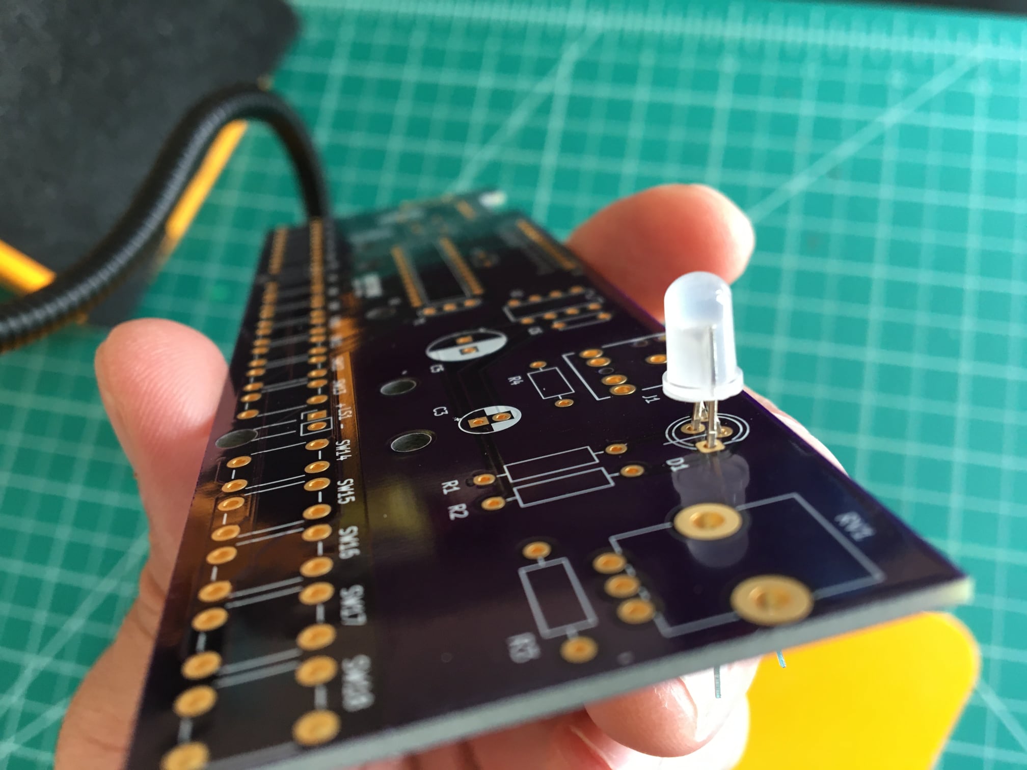
- The LED has four pins for three different colors plus ground. The longest one is to ground and it goes to the hole that has a line coming out of it.
- Solder sliding toggle switch SW1 and resistor R1 (220, Red Red Brown).
- Make sure the switch is flat against the PCB and its actuator is pointing left, away from the PCB.
- You can use a bit of tape or "Blu-Tack" adhesive to hold the switch in place as you solder.
- Wire battery pack to BT1
- Thread the other side of the ribbon cable connected to the battery pack up through the hole near BT1, then strip and solder in place. Make sure the "+" and "-" wires are going to the right places.
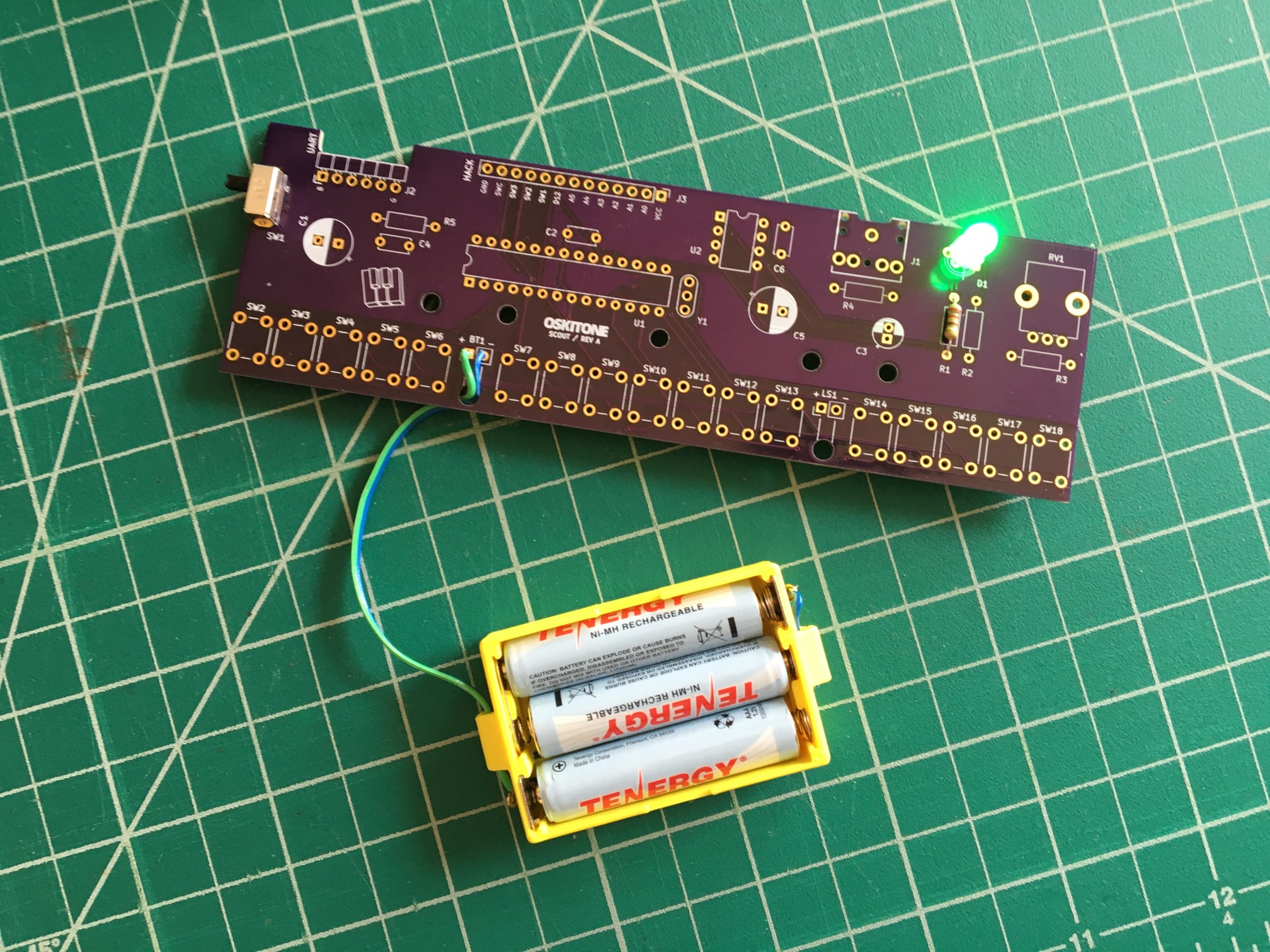
Test
Add the batteries back. Toggling SW1 should now light one color of the LED! Yes, it is bright!! Power off before continuing soldering.
Not working as expected? Check the PCB troubleshooting section. Otherwise, continue to the next step.