Power up
info
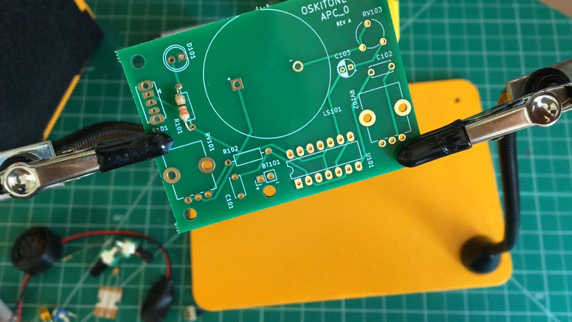
This guide's components' brands and body colors (and even the PCB color itself) may look different from yours, and that's okay! What's important is that the part types and values are in the right spots.
note
Take your time and make sure the LED and switch are perfectly flat against the PCB before soldering all of their pins.
First, we'll get power to the board and make sure our battery is working.
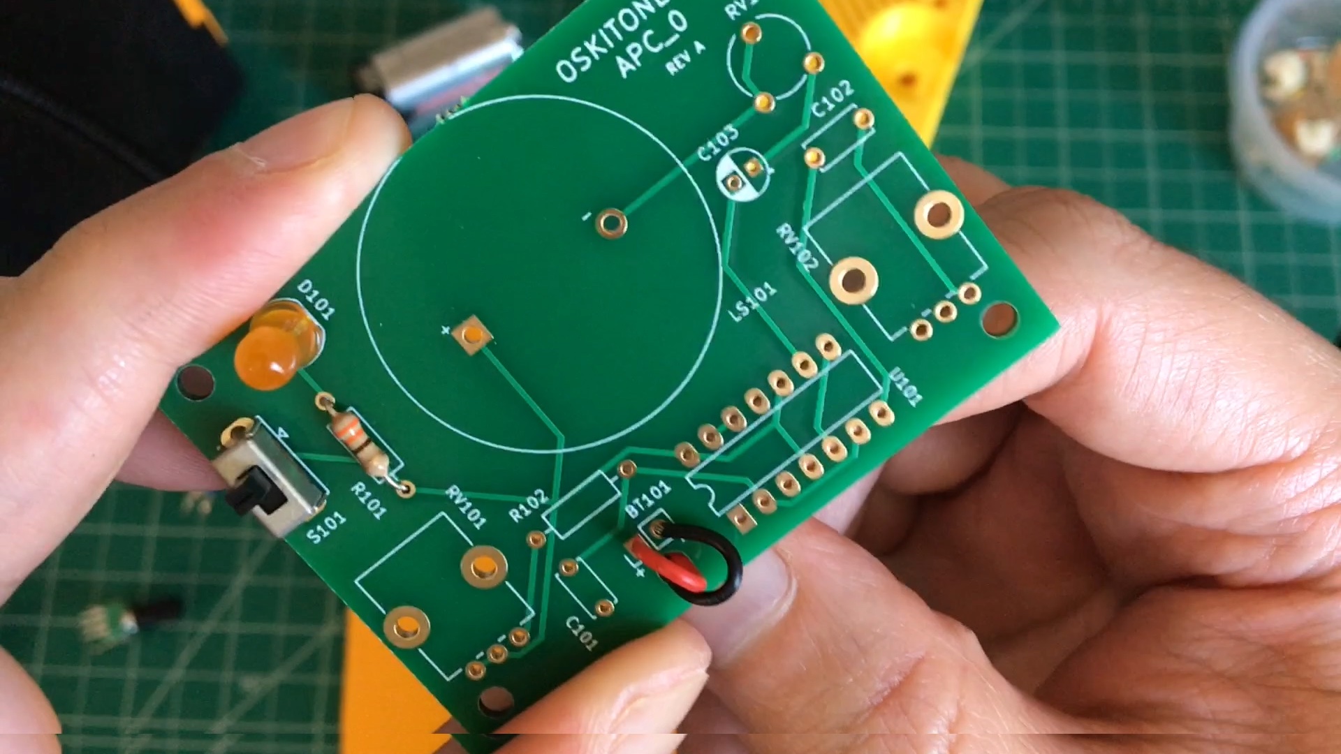
- Find the 330 ohm resistor; its color bands are Orange Orange Brown. Solder it into R101.
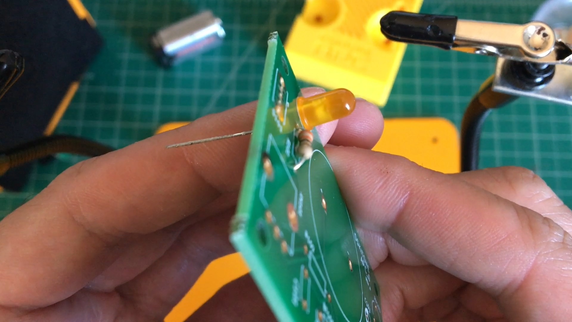
- The LED goes to D101.
- Note that the footprint on the PCB is a circle with one flat side. Insert the LED so its flat side matches that footprint.
- Hold in place and solder. Make sure it's flat against the PCB.
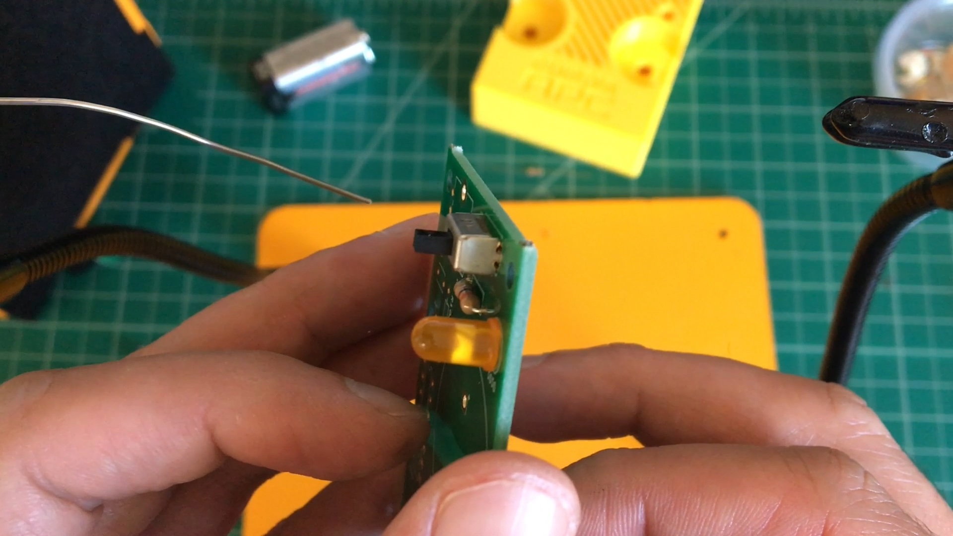
- The slider switch goes to S101.
- It doesn't have polarity and can go in either direction, but, just like the LED, it does need to be perfectly flat against the PCB.
- Confirm it's flat before soldering soldering all of its pads.
- Next up is the 9v battery snap.
- Feed its wires through the hole by BT101. This acts as a stress relief, preventing strain at the solder joints whenever you replace the battery.
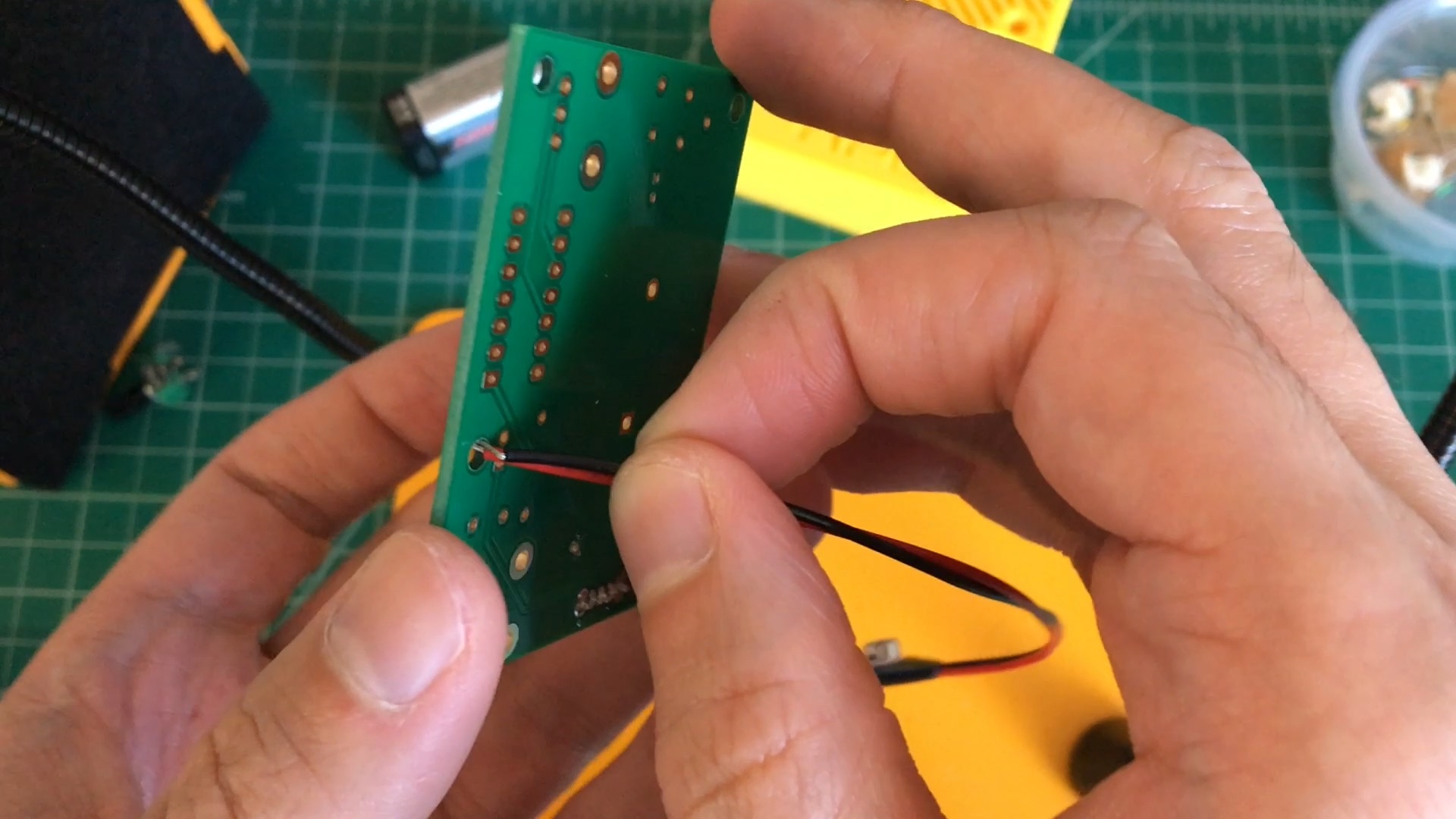
- Insert and solder wires into place: red to + and black to -
- Feed its wires through the hole by BT101. This acts as a stress relief, preventing strain at the solder joints whenever you replace the battery.
- Test it!
- Connect a battery to the 9v snap, and slide the switch back and forth. You should see the LED turn on and off. Nice!
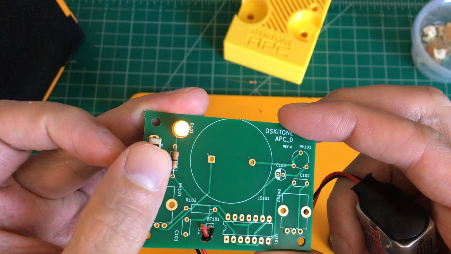
- If you don't, don't worry; it's just time to debug. Don't move on to the next step until you've got this working.
- Check all your solder joints.
- Verify LED is placed correctly and matches its footprint.
- Is the battery dead?
- Are the battery wires in the right spots?
- Connect a battery to the 9v snap, and slide the switch back and forth. You should see the LED turn on and off. Nice!
- Trim leads if you haven't already, and remove the battery before continuing.