Bigger components
note
Take your time and make sure the pots and speaker are perfectly flat against the PCB before soldering all of their pins.
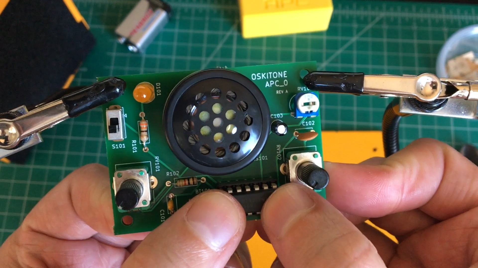
Last is the bigger components: pots, speaker, and IC.
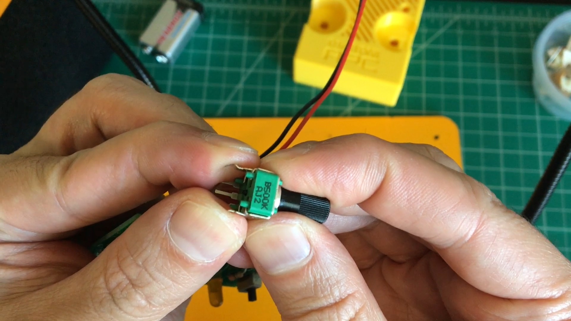
- Push the two 500k pots ("pot" is short for "potentiometer"!) into their footprints at RV101 and RV102
- A trick to get the pot to snap in better is to gently push its mounting tabs inward before popping it onto the PCB.
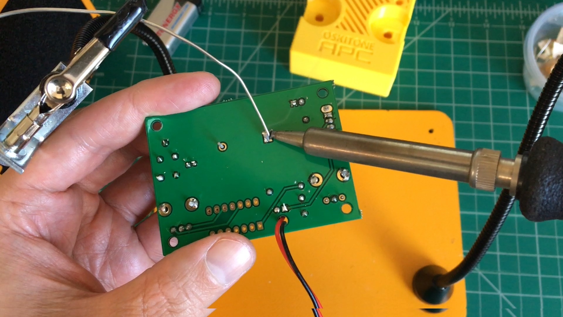
- Check that they're flat against the PCB, then solder into place.
- You can solder the mounting tabs on the side too, if you want!
- A trick to get the pot to snap in better is to gently push its mounting tabs inward before popping it onto the PCB.
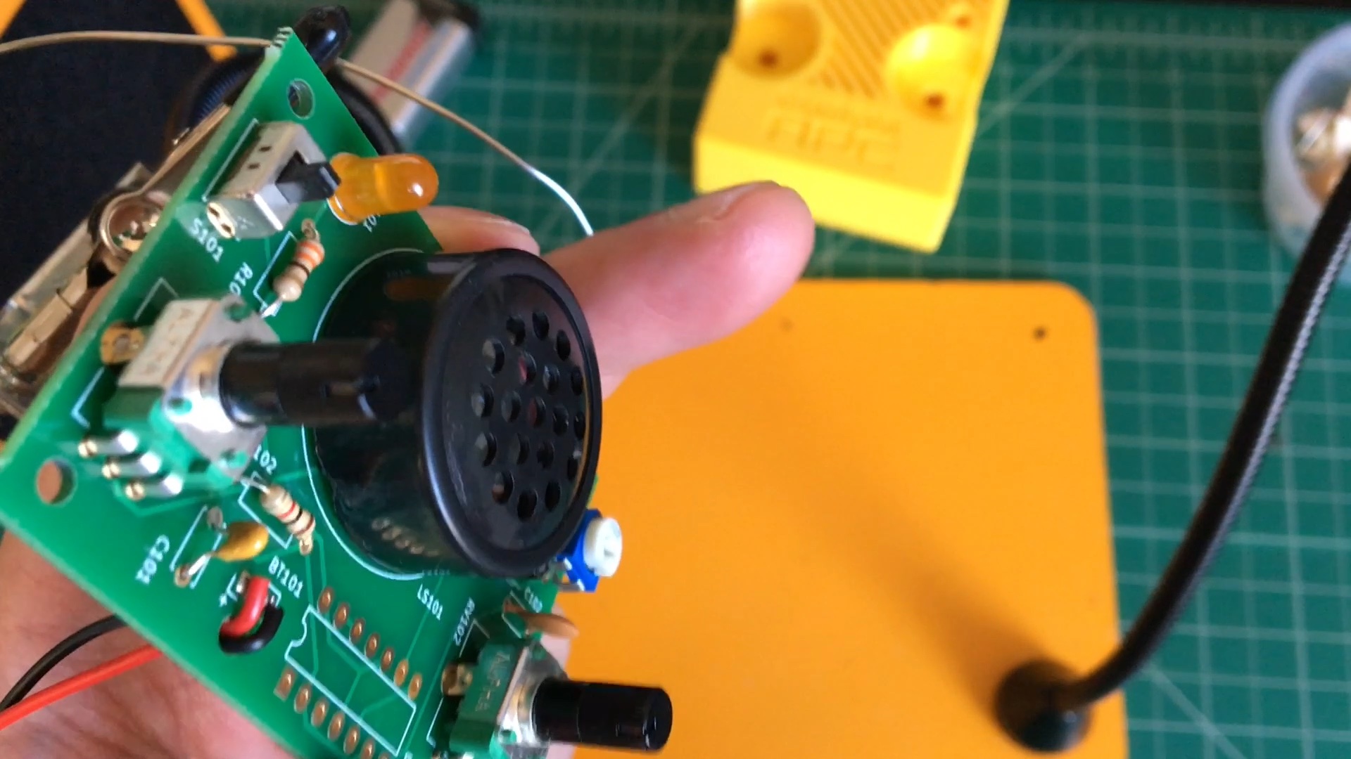
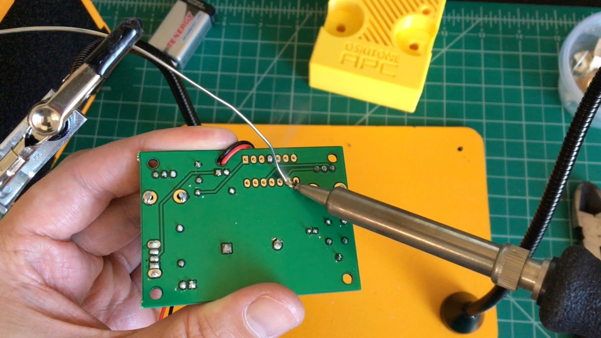
- Fit the speaker into LS101, matching its + and - pins to the right holes.
- Don't bend its leads! That can break it.
- Hold in place and solder.
- Check that the speaker is flat against the PCB before continuing.
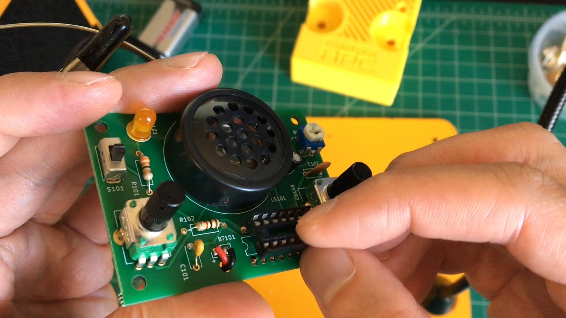
- And the absolute last component to solder is the IC socket
- Place the IC socket into U101, matching its little indentation to the footprint.
- Hold in place and solder.
- Place the IC socket into U101, matching its little indentation to the footprint.
- With its socket soldered, we can add its 556 chip.
- In order to fit well into its socket, the pins of the 556 need to point straight down from the chip's body. You can use a pin straightener tool or simply bend them against any flat surface.
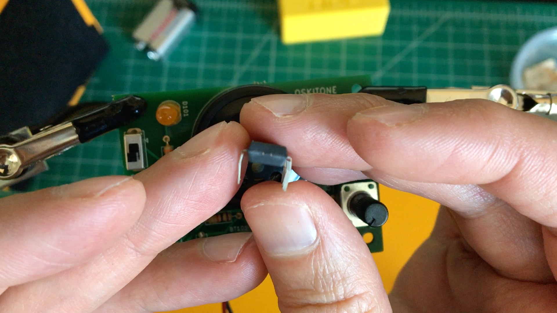
- Carefully insert the 556 chip into the socket at U101, matching its indentation. If its pins don't seem to go in well, try the previous step again.
- In order to fit well into its socket, the pins of the 556 need to point straight down from the chip's body. You can use a pin straightener tool or simply bend them against any flat surface.