PCB Step 5: And All the Rest
Goal#
Finish timer circuits.
tip
You've got this! Keep going!
This step will take the longest time, but, if you've made it this far, it should be relatively straightforward... Everything you're doing here you've already done somewhere else!
Components#
- Timer circuit * 19
- 100k resistor * 1
- 100 resistor * 1
- 10k resistor * 1
- .1uF ceramic capacitor * 1
- 4.7uF electrolytic capacitor * 1
- 10nF ceramic capacitor * 1
- 1k trimmer potentiometer * 1
- IC socket * 1
- 10 resistor * 1
- 555 timer chip * 1
Steps#
Just like we did for the timer in Step 3: Make Some Noise, we'll be soldering up the remaining 19 timers.
Rather than list out all the component footprints by number, it's helpful this time to just go by location. You'll probably find that it's easiest to do them all by type; ie, solder all the resistors before moving onto caps, etc.

It should look something like this when done#
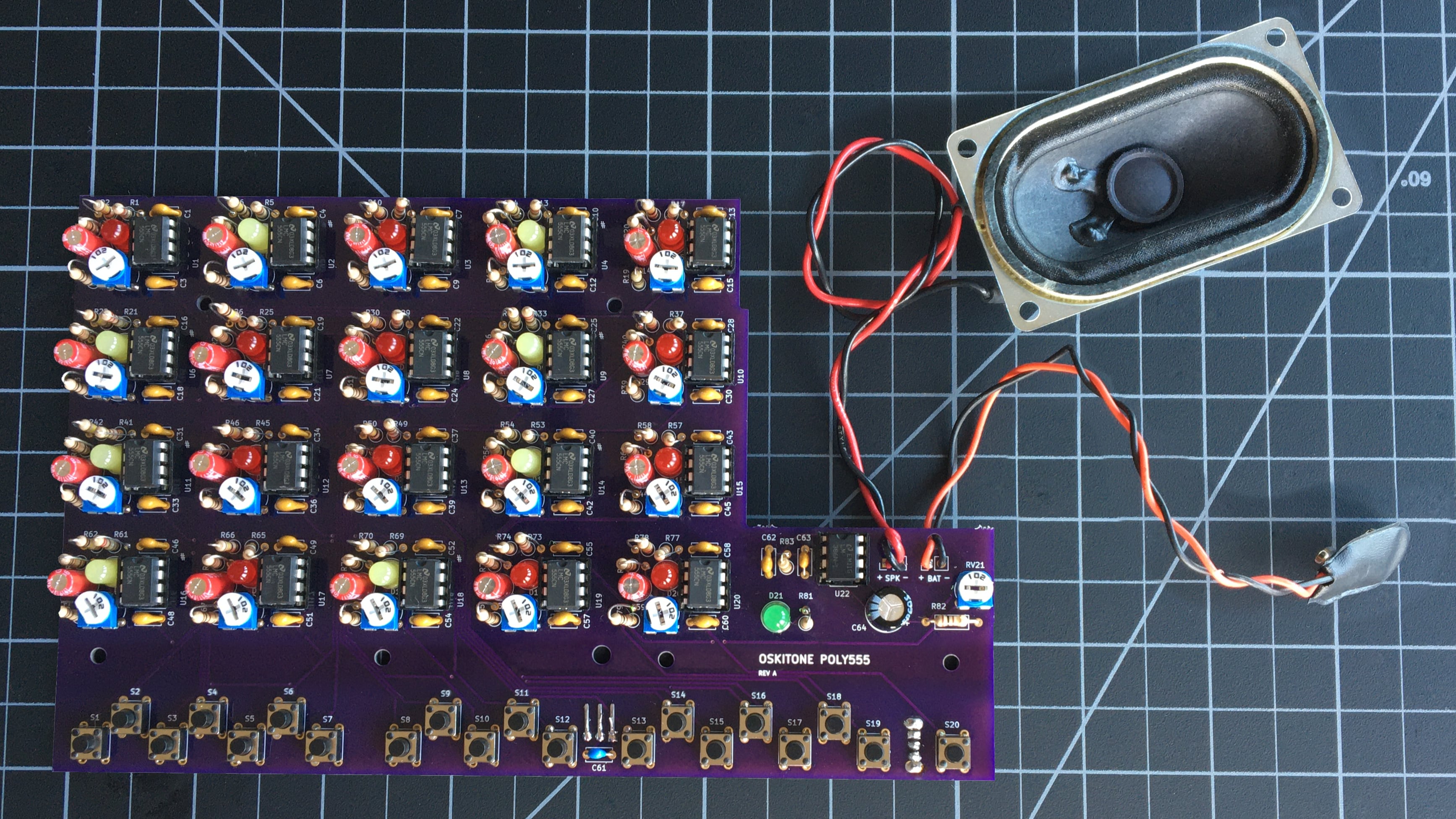
remember
The components' brands and colors for PCB, LEDs, and wires may look different from yours, and that's okay! What's important is that the part types and values are in the right spots.
Test it#
With the battery attached and power switch on, press buttons S2 through S20. You should now hear audible tones out of the speaker!
Troubleshooting#
- Do all the usual debugging steps like checking solder joints, etc.
- Do the same troubleshooting checks you did in Step 3: Make Some Noise but for all the timer circuits.
If all is well, congrats! The hard parts are over. Now's a good time to go wash your hands to get rid of any soldering residue.
How does it work?#
- When any tactile switch is pressed, 5v from the regulator travels up to its corresponding timer circuit, lighting its LED and powering its 555.
Just like in PCB Step 3: Make Some Noise!