PCB Step 4: Light All Lights
Goal#
Solder all the buttons and LEDs.
Components#
- Tactile switch * 19
- 220 resistor * 19
- Natural key LED * 11
- Accidental key LED * 8
Steps#
tip
Double check to make sure you've got the correct LED colors before soldering!
- Solder the 19 tactile switches into S2, S3, S4, S5, S6, S7, S8, S9, S10, S11, S12, S13, S14, S15, S16, S17, S18, S19, and S20. Make sure they're perfectly flat against the PCB, just like S1!
- Solder 19 220 resistors to R5, R9, R13, R17, R21, R25, R29, R33, R37, R41, R45, R49, R53, R57, R61, R65, R69, R73, and R77.
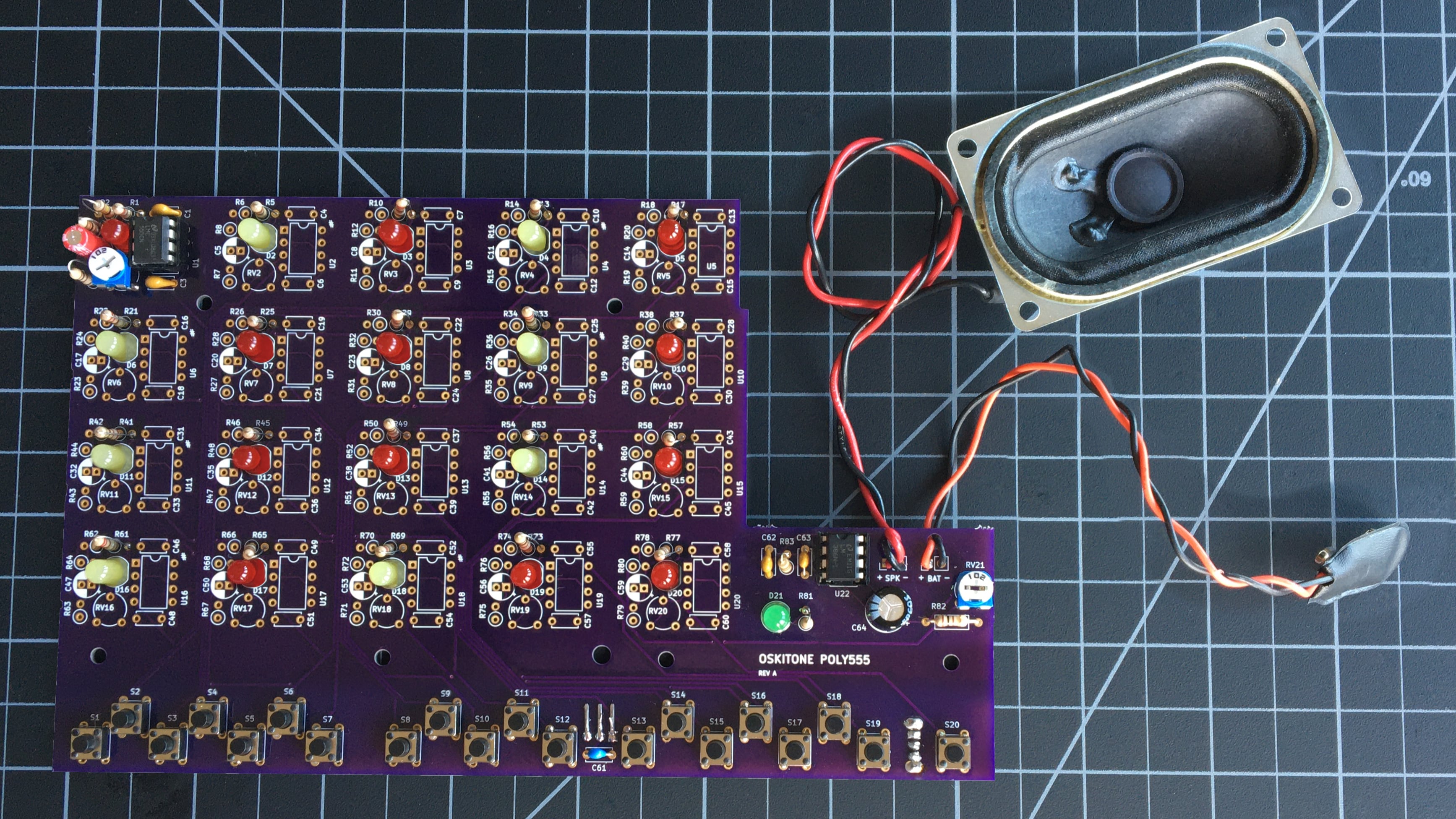
- Solder the remaining 11 LEDs for the natural keys to D3, D5, D7, D8, D10, D12, D13, D15, D17, D19, D20.
- Solder the 8 LEDs for the accidental keys to D2, D4, D6, D9, D11, D14, D16, and D18.
It should look something like this when done#
remember
The components' brands and colors for PCB, LEDs, and wires may look different from yours, and that's okay! What's important is that the part types and values are in the right spots.
Test it#
With the battery attached and power switch on, press buttons S2 through S20. You should see each of its corresponding LEDs light up, just like S1!
Troubleshooting#
- Do all the usual debugging steps like checking solder joints, etc.
- Do the same troubleshooting checks you did in Step 2: Timer LED Power for all the buttons and LEDs.
How does it work?#
- When any tactile switch is pressed, 5v from the regulator travels up to its corresponding timer circuit.
- Its LED lights up, with help from its current-limiting 220 resistor.
Just like in PCB Step 2: Timer LED Power!
