PCB General Tips
caution
These general tips will apply to all PCB assembly steps, so read them and follow them carefully!
General Tips#
- IC chips are static-sensitive
The included IC chips can be damaged by static electricity. Leave them in their packaging until ready to install. Before handling, discharge any static electricity on your body by touching a large piece of metal. You can even use an anti-static mat and/or wrist strap for extra caution. - Ceramic and electrolytic capacitors
There are two kinds of “caps” used in this kit. Ceramic capacitors are small, circular, and have no polarity; they can be placed in either direction. Electrolytic caps are bigger, cylindrical, and have marked +/- polarities. - Vertical resistors
To save space, most resistors stand vertically instead of lay flat on the PCB. - ICs in sockets
Each IC chip comes with a corresponding socket with the same number of pins. You will solder the socket to the PCB, not the chip itself. This prevents overheating the IC with the soldering iron and makes it easier to switch a faulty one out. - Component polarities
LEDs, batteries, and electrolytic capacitors have positive and negative leads. Where applicable, the PCB will be labeled where each lead goes or a component outline to denote orientation. - IC orientation
The IC chips also have an orientation, marked by a notch at their top. Make sure these line up when soldering the sockets and again when inserting the chips. A chip can be permanently damaged if inserted incorrectly! - Not all components go on the front
Take a look at the back side of the PCB and note that there are outlines for two components: U21 (the 7805 voltage regulator) and S21 (the power switch). Unlike all the others, these two will mount on the back. - Wire relief holes
The wires for the speaker (SPK) and battery (BAT) first go through corresponding holes before being soldered. These are meant to reduce strain on the wires as you work on the PCB.
Component Legend#
Component Prefixes#
| Prefix | Type |
|---|---|
| C* | Capacitor (both electrolytic and cermaic) |
| D* | LED |
| R* | Resistor |
| RV* | Resistor Variable (trimpot) |
| S* | Switch |
| U* | IC socket and chip |
Resistors#
| Value | Count | Color Code |
|---|---|---|
| 10 | 1 | Brown Black Black |
| 100 | 21 | Brown Black Brown |
| 220 | 21 | Red Red Brown |
| 10k | 20 | Brown Black Orange |
| 100k | 20 | Brown Black Yellow |
Capacitors#
| Value | Count | Type | Marking |
|---|---|---|---|
| 10nF (or .01uF) | 20 | ceramic | 103 |
| 47nF (or .046uF) | 1 | ceramic | 473 |
| .1uF | 21 | ceramic | 104 |
| .22uF | 1 | ceramic | 224 |
| 4.7uF | 20 | electrolytic | n/a |
| 220uF | 1 | electrolytic | n/a |
LEDs#
You'll have 21 LEDs total in your kit in 3 different colors:
- 1 for the power indicator
- 12 for the natural keys
- 8 for the accidental keys
note
The exact colors for each may vary across kits, which is why they're not denoted here.
When you're soldering the LEDs, make sure to follow the instructions to use the right one for the job.
Order of Operations#
There's nothing worse than working super hard on something for hours until, when you think you've finally got it all finished and ready, you try to turn it on and find out it doesn't work...
To try to prevent that frustration, we're going to put this together incrementally. At each step, we'll solder up the fewest parts possible to verify it's working as expected before moving on to the next step.
- On and Off:
Get power to the board and switch the main LED on and off - Timer LED Power:
Get power to one of the timer circuits and light its LED - Make Some Noise:
Finish the timer circuit, add the amp circuit, and test the speaker - Light All Lights:
Solder all the buttons and LEDs - And All the Rest:
Finish timer circuits
This order should hopefully give you a better understanding of how it all works too!
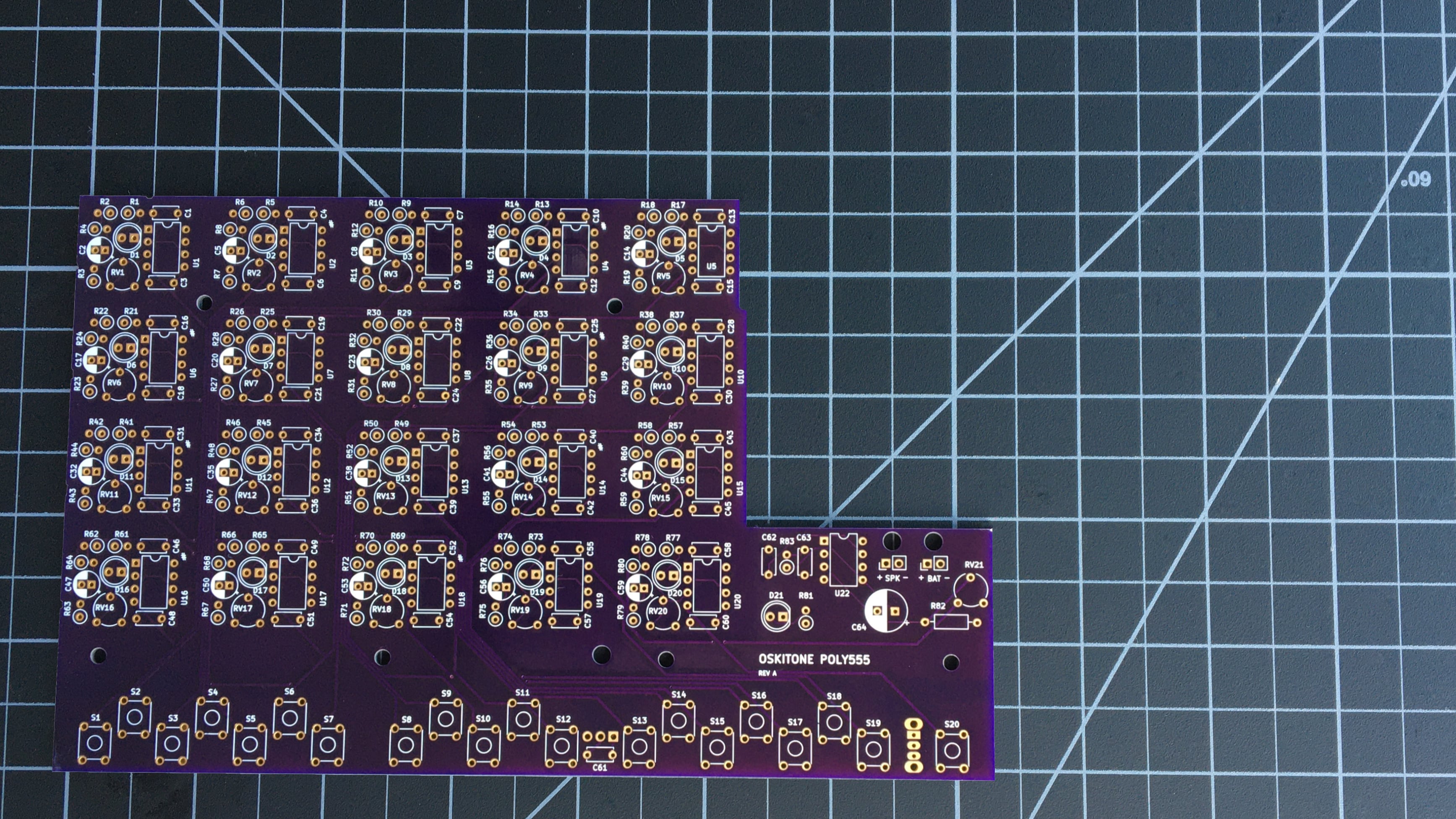
It will look like this before you start#