PCB Step 3: Make Some Noise
Goal#
Finish the timer circuit, add the amp circuit, and test the speaker.
Components#
- Timer circuit
- 100k resistor * 1
- 100 resistor * 1
- 10k resistor * 1
- .1uF ceramic capacitor * 1
- 4.7uF electrolytic capacitor * 1
- 10nF ceramic capacitor * 1
- 1k trimmer potentiometer * 1
- IC socket * 1
- 555 timer chip * 1
- Amp circuit
- .1uF ceramic capacitor * 1
- 47nF ceramic capacitor * 1
- 10 resistor * 1
- IC socket * 1
- 220uF electrolytic capacitor * 1
- 1k trimmer potentiometer * 1
- 100 resistor * 1
- speaker * 1
- 386 amp chip * 1
Steps#
- Finish that first timer circuit
- Solder the 100k resistor to R2.
- Solder a 100 resistor to R3.
- Solder the 10k resistor to R4.
- Solder a .1uF ceramic capacitor to C1.
- Solder the 4.7uF electrolytic capacitor to C2.
- Solder the 10nF ceramic capacitor to C3.
- Solder a 1k trimmer potentiometer into RV1.
- Solder an IC socket into U1.
- The legs of the socket may be bent from shipping. Make sure they're all straight and intact when inserting into PCB and before soldering. De-soldering a damaged socket is no fun! Do this for all the IC sockets for the rest of the assembly process.
- Solder the amp circuit
- Solder a .1uF ceramic capacitor to C62.
- Solder the 47nF ceramic capacitor to C63.
- Solder 10 resistor to R83.
- Solder an IC socket into U22.
- Solder the 220uF electrolytic capacitor to C64
- Solder a 1k trimmer potentiometer into RV21.
- Solder a 100 resistor to R82.
- Solder the speaker.
- Strip about 1/8" of the insulation off wire's ends.
- If necessary, solder wires to speaker. The lighter wire goes to + and the darker wire goes to -.
- Just like you did for the battery snap, feed wires through the relief hole above SPK, then solder them into place: lighter wire to + and darker to -.
- Insert IC chips
- Insert the 555 timer chip into its socket at U1, making sure it's in the right orientation: a notch or dimple at the top of the chip should match the notch in the footprint outline on the PCB.
- Insert the 386 amp chip into its socket at U22, again making sure its in the right orientation. You'll do this for all chips throughout assembly.
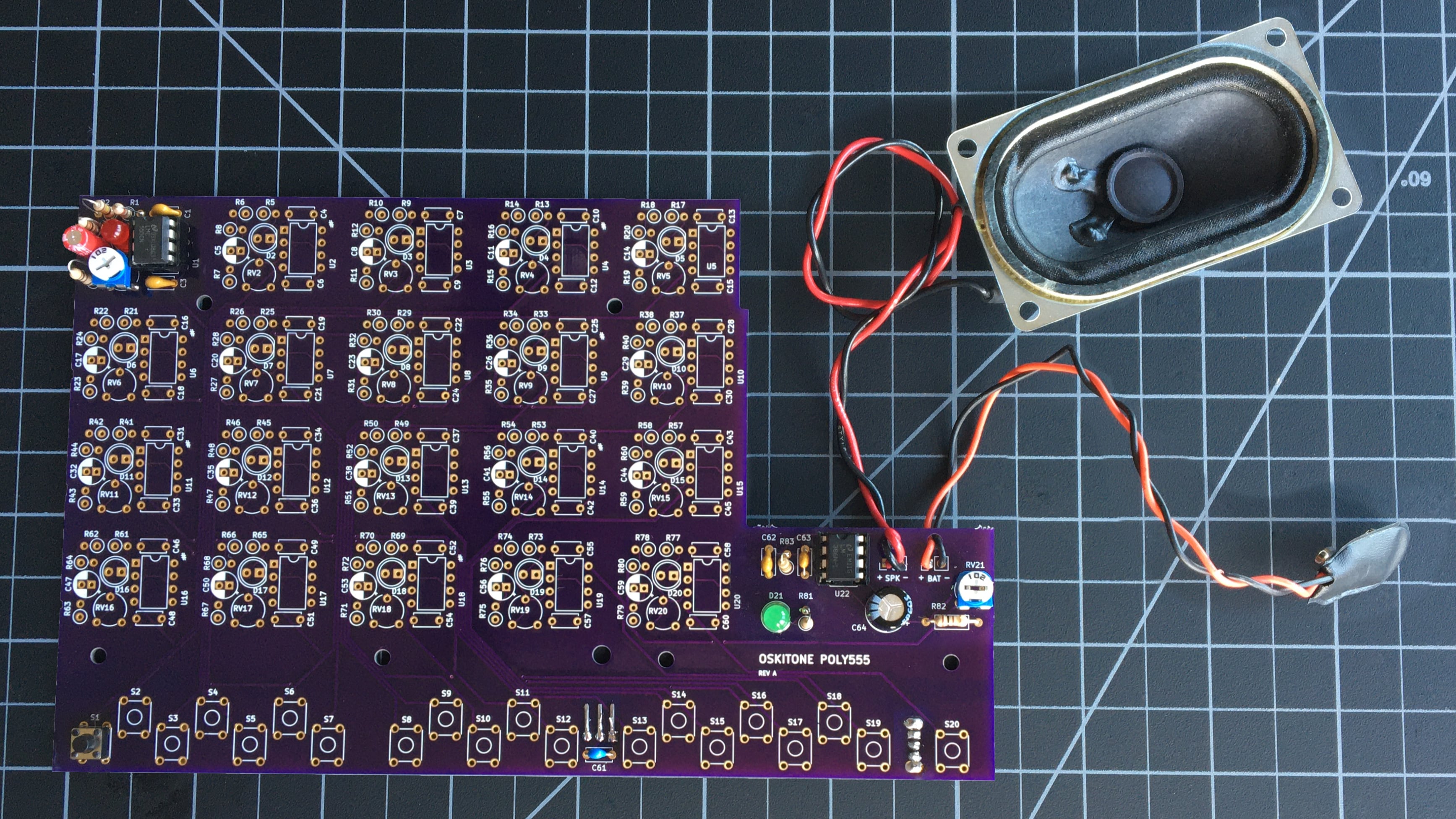
It should look something like this when done#
remember
The components' brands and colors for PCB, LEDs, and wires may look different from yours, and that's okay! What's important is that the part types and values are in the right spots.
Test it#
- With the battery attached, turn the power switch on. You should hear a little "boomp" noise from the speaker as it's powered by the amp.
- Press S1 again. In addition to the LED being lit, you should now hear an audible tone out of the speaker!
- Try adjusting the pot at RV1. Turning it clockwise should make the frequency go up, and vice-versa.
- Try the same on the volume pot at RV21. Clockwise should make the sound quieter, and counter-clockwise will be louder.
Troubleshooting#
- Do all the usual debugging steps like checking solder joints, etc.
- Check to see that the volume potentiometer at RV21 isn't turned all the way down.
How does it work?#
- First, the 555 timer circuit
- The .1uF ceramic capacitor at C1 is what's called a "bypass cap" and reduces voltage fluctuations as the chip pulls in power.
- The frequency of the timer is set by the 4.7uF electrolytic capacitor at C2, the 100k resistor at R2, the 100 resistor at R3, and the 1k trimmer potentiometer (aka "variable resistor") at RV1. R3 and RV1 are connected serially and their values sum together — the range of available resistances is, roughly, 100 to 1100.
- The 10nF ceramic capacitor at C3 ties the 555's "control voltage" pin to ground. You may see other 555 oscillator circuits that use an analog voltage on this pin to control its frequency, but, since ours is tuned with the pot at RV1, we just bring it down to ground, which will always be 0v.
- When the switch at S1 is pressed, power is supplied to its LED and this 555 chip. A square wave outputs from its pin 3 and goes through the 10k resistor at R4 before heading off to the amp circuit. This resistor is a "mixer" and prevents the other timers' outputs from interfering with each other.
- Next, the 386 amp
- The timers' output mixing resistors all connect at one of the pins of our volume pot, the 1k trimmer potentiometer at RV21, which is wired as a voltage divider. Depending on where the pot is set, a certain amount of sound is either dumped to ground or sent off to be amplified.
- The 100 resistor at R82 connects across two of the pins of the volume pot and changes the sweep of the pot from linear to something closer to logarithmic, which is what our ears expect to hear.
- The .1uF ceramic capacitor at C62 is another bypass cap and helps to prevent static noise from the amp.
- The 10 resistor at R83 and 47nF ceramic capacitor at C63 act as a "snubber" to suppress the amp from triggering itself into oscillation.
- Output from the amp goes through the 220uF electrolytic capacitor at C64 before connecting to the speaker.
