PCB Step 2: Timer LED Power
Goal#
Get power to one of the timer circuits and light its LED
Components#
- .22uF ceramic capacitor * 1
- 7805 voltage regulator * 1
- Tactile switch * 1
- 1/4" screw * 1
- Nut * 1
- 220 resistor * 1
- Natural key LED * 1
Steps#
tip
Double check to make sure you've got the correct LED color before soldering!
- Solder the .22uF ceramic capacitor to C61.
- Solder the 7805 voltage regulator to U21.
- It will lay flat against its outline on the back of the PCB, with its text facing outwards, its tab pressed firmly against the exposed copper rectangle on ther PCB, and its legs bent into their holes. To help hold it there while soldering, attach its tab to the PCB with the screw and nut. It's important that there's no visible gap between 7805's tab and the copper plate on the PCB.
- Solder its legs on the front of the PCB.
- Solder its tab to the copper plate on the back of the PCB by applying solder to the sides of the tab where it meets the copper plate. You may need to use a higher temperature on your soldering iron and/or apply additional flux if using a non-flux solder.
- Remove the screw and nut for later use.
- Solder a tactile switch into S1, making sure it's perfectly flat against the PCB.
- A trick I like to do is to solder just one of its legs to hold it in place, then remelt the solder while pushing it in from the other side.
- Solder a 220 resistor to R1.
- Solder the LED to D1, making sure to match its outline.
It should look something like this when done#
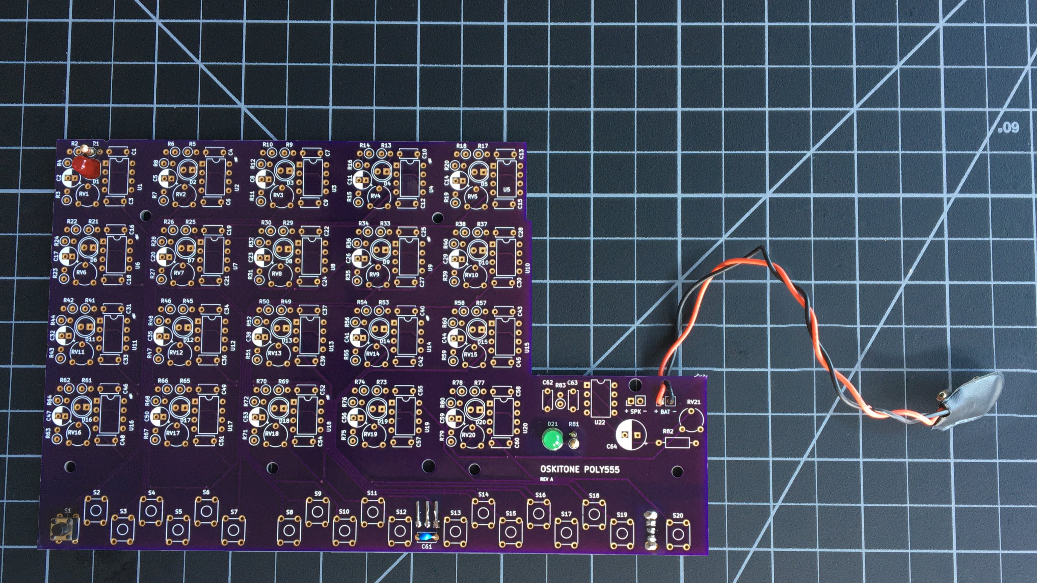
remember
The components' brands and colors for PCB, LEDs, and wires may look different from yours, and that's okay! What's important is that the part types and values are in the right spots.
Test it#
With the battery attached and power switch on, press S1. You should see the LED at D1 turn on!
Troubleshooting#
- Do all the usual debugging steps like checking solder joints, etc.
- Use a multimeter to confirm 7805 has 9v going in and 5v coming out, then confirm that's going from the button to R1 when pressed.
How does it work?#
- The 7805 voltage regulator at U21 takes 9v from the battery and brings it down to 5v.
- Why would we want to do this? The 555 timers we'll solder next are sensitive to changes in voltage, and our 9v battery will slowly supply less juice as the POLY555 is used. The 7805 regulates that dwindling voltage so it's a consistent 5v. Without the regulator, the timers would quickly fall out of tune!
- A side effect of how the 7805 works is that it creates heat — after all, that extra power has to go somewhere, right? That heat is dissipated through its tab and distributed into the "ground" of the PCB.
- The cap at C61 helps to reduce fluctuations in the output voltage.
- When the tactile switch at S1 is pressed, 5v from the regulator travels up to the first timer circuit in the board's top left corner.
- Just like the LED from the previous step, the LED at D1 has a 220 resistor at R1 to limit its current to a less-destructive value.