PCB Step 1: On and Off
Goal#
Get power to the board and switch the main LED on and off.
Components#
- Sliding toggle switch * 1
- 9v battery snap * 1
- 220 resistor * 1
- Power indicator LED * 1
Steps#
tip
Double check to make sure you've got the correct LED color before soldering!
tip
The S21 switch goes on the back of the PCB, not the front.
- Solder the sliding toggle switch to S21 on the back of the PCB. There's no polarity to this component, so either way is fine as long as it's on the back side.
- Feed the battery snap's wires through the relief hole above BAT, then solder its wires into place: red for + and black for -.
- Solder a 220 resistor to R81.
- Solder the LED to D21, making sure to match its outline.
It should look something like this when done#
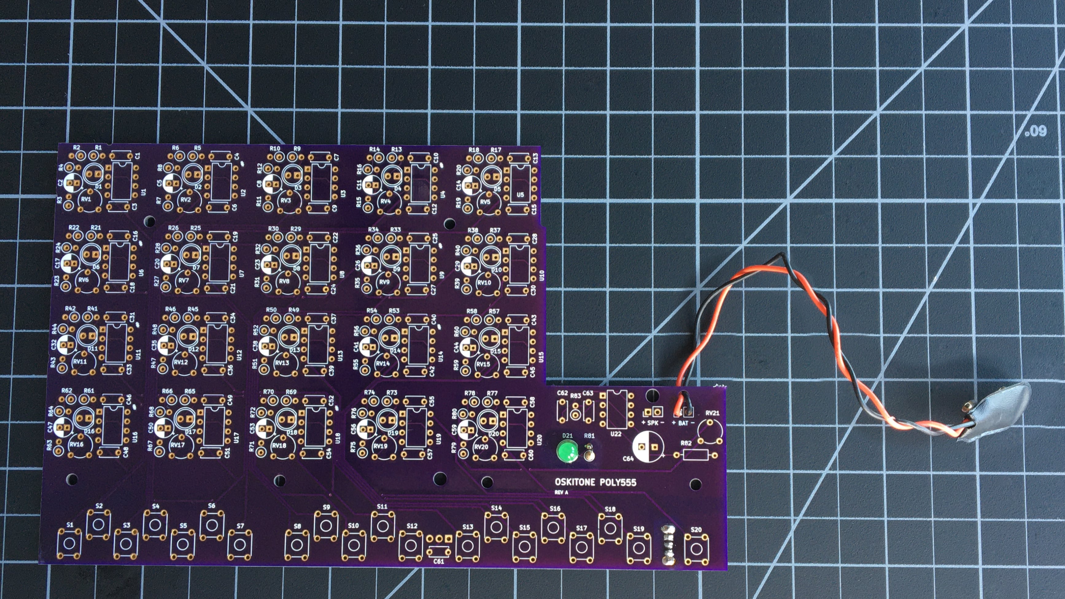
remember
The components' brands and colors for PCB, LEDs, and wires may look different from yours, and that's okay! What's important is that the part types and values are in the right spots.
Test it#
Connect your battery and slide the switch back and forth. You should see the LED turn on and off!
If you have the enclosure bottom handy, you can also try inserting the PCB into it. The switch should fit nicely into its cavity and be exposed on the other side, and the screw holes should align with their counterparts.
Troubleshooting#
- Do all the usual debugging steps like checking solder joints, etc.
- Use a multimeter to confirm power is getting from battery to switch to R81 to LED
- If power is getting to LED but it isn't lighting, it may be dead. Try a different one.
How does it work?#
- The battery snap connects the 9v battery to the PCB. Its negative wire (ground) goes throughout the board, but its positive wire only goes to the sliding toggle switch at S21.
- When the sliding toggle switch is on, power goes from the battery to the rest of the circuit. When it's switched off, no power is used. S21 acts like manually connecting and disconnecting the battery.
- The first part of the circuit to use the battery's power is the LED at D21, but first it goes through the 220 resistor to R81. This is called a current-limiting resistor. Without it, the LED would burn out!