How Does It Work?
Inside the enclosure and under the keys is this PCB:
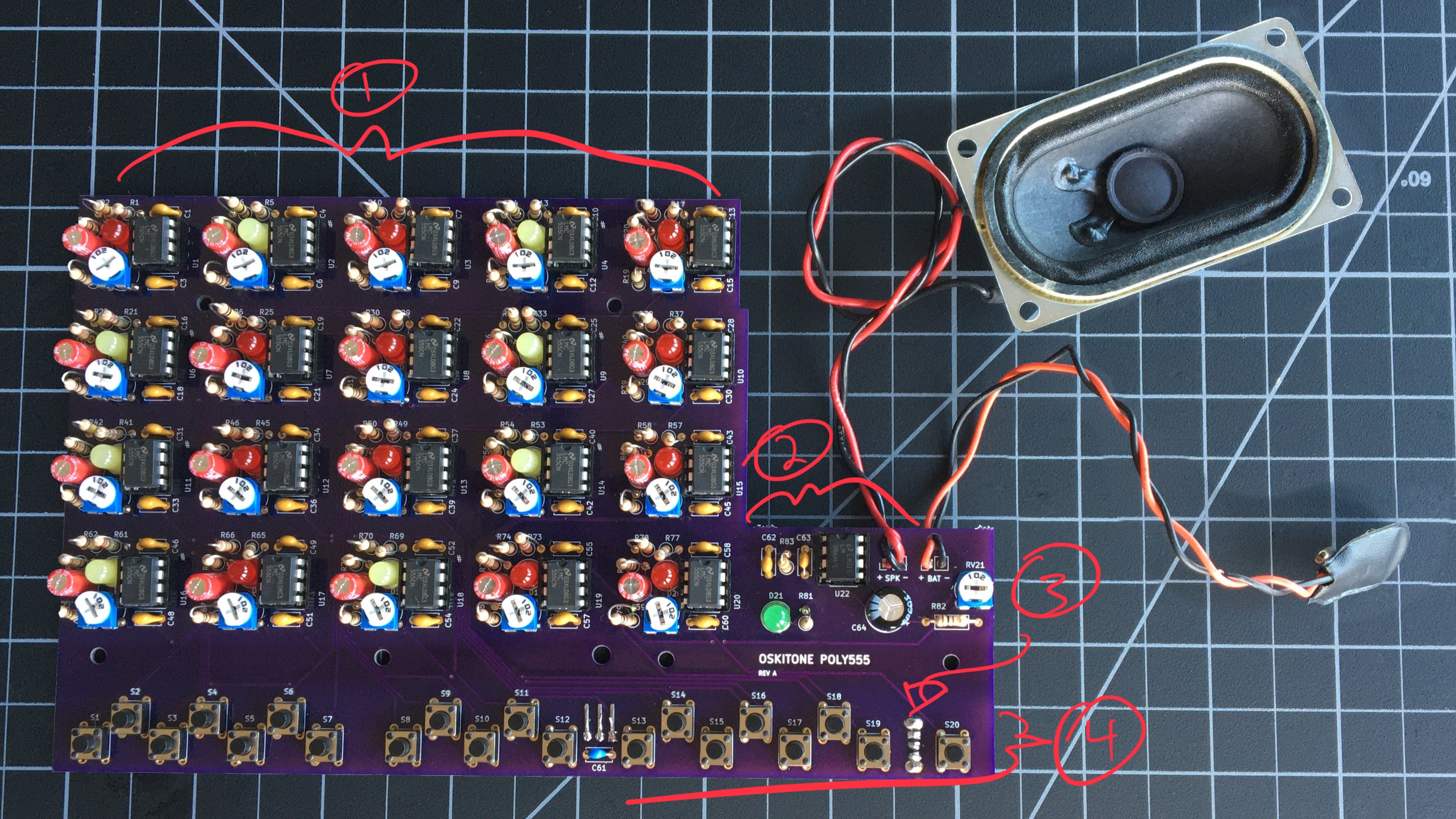
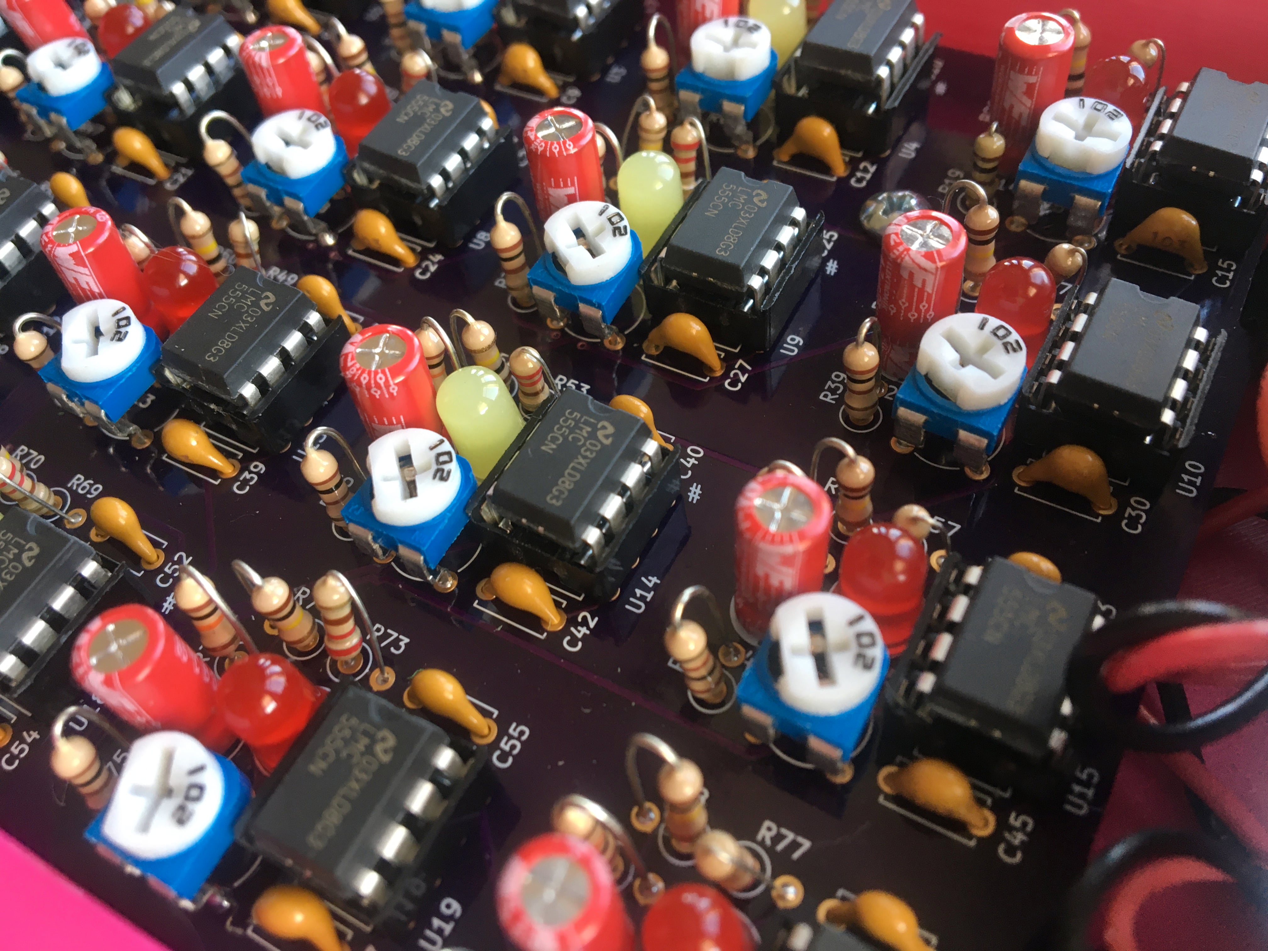
- 555 timers
Twenty identical timer circuits are laid out in 4 rows of 5 columns. They'll be exposed for adoration by a plexiglass window. - Amp
A simple amplifier drives the speaker. Its volume control is exposed on the right of the enclosure. - Power
A 9v battery powers the device, which is toggled by a sliding toggle switch on the PCB's back. An LED lights up when it's on. - Buttons and regulator
Power from the switched 9v battery is regulated down to 5v by a 7805 regulator, then distributed across 20 tactile switches -- one for each timer circuit above. Regulating the voltage to a fixed 5v keeps the timers' frequencies consistent even as the battery drains.
For a deeper dive into the underlying circuit, head over to the schematics.
The keys to the keys to the timers#
The switches and their timer circuits correspond numerically: S1 to U1, S2 to U2, etc.
All the timer circuits are internally identical, so, for example, the resistors are always in the same places -- once you know how where they go in one circuit, you know how to do all of them.
The circuits for the accidental keys (F#, G#, A#, C#, D#) are marked with a # beside their IC socket.